Hyundai Ioniq: Hybrid Control System / DC Fuse. Repair procedures
Hyundai Ioniq (AE) 2017-2025 Service Manual / Hybrid Control System / Hybrid Control System / DC Fuse. Repair procedures
| Removal |
|

| 1. | Shut off the High Voltage circuit (Refer to Hybrid Control System - "High Voltage Shut-off Procedures") |
| 2. | Remove the air cleaner assembly and duct. (Refer to Engine Mechanical System - "Air Cleaner") |
| 3. | Disconnect the power cable (A) [↔ High voltage battery system assembly] and inverter power cable (B) [↔ HSG & Electric A/C compressor].
|


| 4. | Remove the DC fuse cover (A) after loosening the mounting bolt.
|

| 5. | Remove the DC fuse seal cover (A).
|

| 6. | Remove the DC fuse (A) from the HPCU after loosening the mounting bolt.
|

| Installation |
|
| 1. | Install the DC fuse in the reverse order of removal. |


Other information:
Hyundai Ioniq (AE) 2017-2025 Owner's Manual: Highway Driving
Tires Adjust the tire inflation, as specified. Under-inflation may overheat or damage the tires. Do not install worn-out or damaged tires, which may reduce traction or adversely affect vehicle handling. This could lead to sudden tire failure that may cause loss of vehicle control resulting in an accident...
Hyundai Ioniq (AE) 2017-2025 Service Manual: Rear Transverse Trim. Repair procedures
Replacement • Put on gloves to prevent hand injuries. • When removing with a flat-tip screwdriver or remover, wrap protective tape around the tools to prevent damage to components...
Categories
- Manuals Home
- 1st Generation Ioniq Owners Manual
- 1st Generation Ioniq Service Manual
- Hybrid battery SOC (State of Charge) gauge
- Check Hybrid system, Check Hybrid system. Turn engine Off
- Checking the Coolant Level
- New on site
- Most important about car
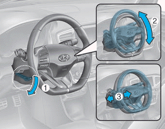
Tilt Steering / Telescope Steering
Adjust the steering wheel so it points toward your chest, not toward your face. Make sure you can see the instrument cluster warning lights and gauges. After adjusting, push the steering wheel both up and down to be certain it is locked in position. Always adjust the position of the steering wheel before driving.
WARNING
NEVER adjust the steering wheel while driving. This may cause loss of vehicle control resulting in an accident.

Copyright © 2025 www.hioniqae.com