Hyundai Ioniq (AE): Brake System / Front Disc Brake. Repair procedures
| Removal |
| 1. | Loosen the wheel nuts slightly. Raise the vehicle, and make sure it is securely supported. |
| 2. | Remove the front wheel and tire (A) from the front hub.
|

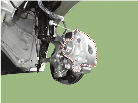
| 3. | Loosen the brake hose mounting bolt and then remove the brake hose bracket.
|

| 4. | Put down the caliper body after loosening the guide rod bolt.
|
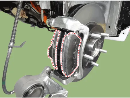
| 5. | Remove the pad return spring (A).
|


| 6. | Remove the brake pad.
|
| 7. | Separate the pad retainer. And remove the caliper carrier by loosening the caliper mounting bolts.
|
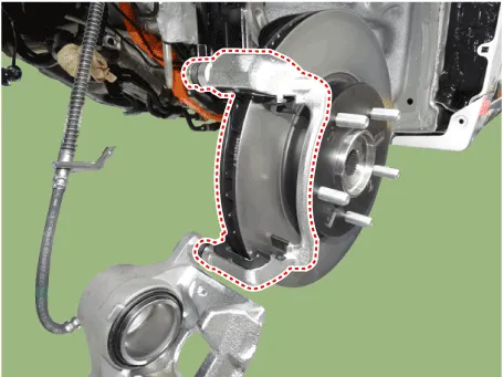
| 8. | Remove the front brake disc by loosening the screws.
|

| Replacement |
| 1. | Loosen the wheel nuts slightly. Raise the vehicle, and make sure it is securely supported. |
| 2. | Remove the front wheel and tire (A) from the front hub.
|
| 3. | Loosen the brake hose mounting bolt and then remove the brake hose bracket.
|
| 4. | Put down the caliper body after loosening the guide rod bolt.
|
| 5. | Remove the pad return spring (A).
|
| 6. | Remove the brake pad.
|
| 7. | Install the pad return spring (A).
|
| 8. | Use a SST (09581-2T100) when installing the brake caliper assembly.
|

| 9. | Install the caliper body (A) then tighten the guide rod bolt (B).
|

| Inspection |
| 1. | Check the brake pads for wear and fade. |
| 2. | Check the brake disc for damage and cracks. |
| 3. | Remove all rust and contamination from the surface, and measure the disc thickness at 24 points, at least, of same distance (5mm) from the brake disc outer circle.
|

| 4. | If wear exceeds the limit, replace the discs and pad assembly left and right of the vehicle. |
| 1. | Check the pad wear. Measure the pad thickness and replace it, if it is less than the specified value.
|
| 2. | Check that grease is applied, to sliding contact points. Check for metal damage to the pad and backing.
|

| 1. | Place a dial gauge about 10mm (0.2 in.) from the outer circumference of the brake disc, and measure the runout of the disc.
|

| 2. | If the runout of the brake disc exceeds the limit specification, replace the disc, and then measure the runout again. |
| 3. | If the runout does not meet the limit specification, remove the disc, turn it 180° and reinstall. Then check the runout of the brake disc again. |
| 4. | If the runout cannot be corrected by changing the position of the brake disc, replace the brake disc. |
| Installation |
| 1. | To install, reverse the removal procedure. |
| 2. | Use a SST (09581-2T100) when installing the brake caliper assembly.
|
| 3. | After installing, bleed the brake system. (Refer to Brake System - "ESP System Bleeding") |
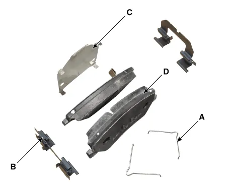
Components1. Bleed screw2. Caliper body3. Pad inner shim4. Brake pad5. Pad return spring6. Caliper carrier7. Pad retainer
Components[EPB None Apply]1. Brake pad2. Pad return spring3. Caliper carrier4. Pad retainer5. Caliper body6. Bleed screw7. Stopper8. Return spring9. Operating lever[EPB Apply]1.
Other information:
Hyundai Ioniq (AE) 2017-2022 Service & Repair Manual: Auto Defogging Sensor. Repair procedures
Diagnosis With GDS1.The heating, ventilation and air conditioning can be quickly diagnosed failed parts with vehicle diagnostic system (GDS).※ The diagnostic system (GDS) provides the following information.(1) Self diagnosis : Checking the failure code (DTC) and display.
Hyundai Ioniq (AE) 2017-2022 Service & Repair Manual: High voltage shut-off procedures
High Voltage Shut-off Procedures • Be sure to read and follow the "General Safety Information and Caution" before doing any work related with the high voltage system. Failure to follow the safety instructions may result in serious electrical injuries.
Categories
- Manuals Home
- Hyundai Ioniq Owners Manual
- Hyundai Ioniq Service Manual
- Audio
- AVN(Audio Video Navigation) head unit. Components and components location
- Maintenance
- New on site
- Most important about car
