Hyundai Ioniq: Driveshaft Assembly / Front Driveshaft. Repair procedures
Hyundai Ioniq (AE) 2017-2025 Service Manual / Driveshaft and axle / Driveshaft Assembly / Front Driveshaft. Repair procedures
| Removal |
| 1. | Loosen the wheel nuts slightly. Raise the vehicle, and make sure it is securely supported. |
| 2. | Remove the front wheel and tire (A) from the front hub.
|

| 3. | Loosen the driveshaft caulking nut (A).
|
| 4. | Remove the tie rod end ball joint.
|
| 5. | Loosen the lower arm nut and then remove the lower arm ball joint by using SST(09568-1S100).
|

| 6. | Using a plastic hammer (A), remove the front driveshaft (B) from the knuckle assembly (C).
|
| 7. | Loosen the inner shaft mounting bolts and then remove the driveshaft RH.
|
| 8. | Insert a pry bar between the transaxle case and joint case, and separate the driveshaft.
|
| 9. | Install in the reverse order of removal. |
| 10. | Check the front alignment. (Refer to Suspension System - "Front Alignment") |


Other information:
Hyundai Ioniq (AE) 2017-2025 Service Manual: Fuel Pump Control Module (FPCM). Repair procedures
Removal1.Turn the ignition switch OFF and disconnect the battery negative (-) cable.2.Remove the rear seat cushion. (Refer to Body - "Rear Seat Assembly")3.Remove the fuel pump service cover (A). • When reinstalling a protective cover for a fuel pump, remove the existing butyl tape and apply a new one...
Hyundai Ioniq (AE) 2017-2025 Owner's Manual: User settings mode
In this mode, you can change the settings of the instrument cluster, doors, lamps, etc. 1. Driver Assistance 2. Door 3. Lights 4. Convenience 5. Service Interval 6. Other (Features) 7. Reset The information provided may differ depending on which functions are applicable to your vehicle...
Categories
- Manuals Home
- 1st Generation Ioniq Owners Manual
- 1st Generation Ioniq Service Manual
- Hybrid battery SOC (State of Charge) gauge
- High Beam Assist (HBA)
- How to Disconnect Normal Charger
- New on site
- Most important about car
Hybrid Vehicle Engine Compartment
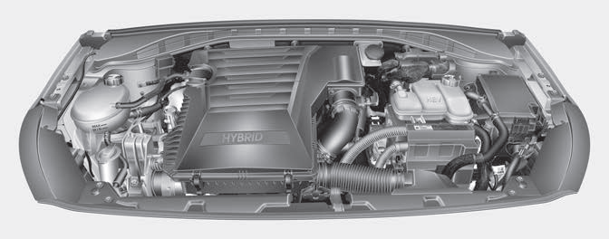
1. Engine oil filler cap
2. Engine oil dipstick
3. Engine coolant cap
4. Engine coolant reservoir
5. Inverter coolant reservoir

Copyright © 2025 www.hioniqae.com