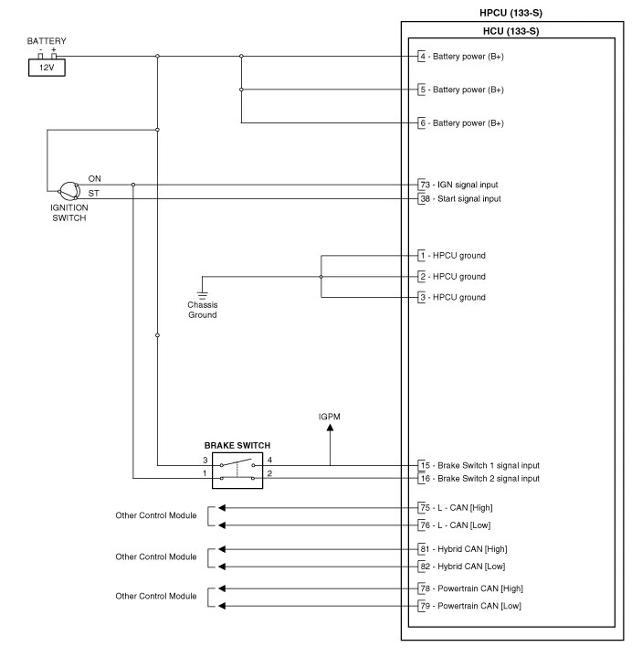
Hyundai Ioniq (AE): Hybrid Control System / HCU (Hybrid Control Unit). Schematic diagrams
| HCU Terminal and Input / Output Signal |

| Terminal Function |
|
Pin No
|
Description
|
Connected to
|
| 1 | HCU Ground | Chassis ground |
| 2 | HCU Ground | Chassis ground |
| 3 | HCU Ground | Chassis ground |
| 4 | Battery power (B+) | Battery |
| 5 | Battery power (B+) | Battery |
| 6 | Battery power (B+) | Battery |
| 7 | - |   |
| 8 | - |   |
| 9 | - |   |
| 10 | - |   |
| 11 | - |   |
| 12 | - |   |
| 13 | - |   |
| 14 | - |   |
| 15 | Brake Switch 2 signal input | Brake Switch (NC, IG1) |
| 16 | Brake Switch 1 signal input | Brake Switch (NO, B+) |
| 17 | - |   |
| 18 | - |   |
| 19 | - |   |
| 20 | - |   |
| 21 | - |   |
| 22 | - |   |
| 23 | - |   |
| 24 | - |   |
| 25 | - |   |
| 26 | - |   |
| 27 | - |   |
| 28 | - |   |
| 29 | - |   |
| 30 | - |   |
| 31 | - | |
| 32 | - | |
| 33 | - | |
| 34 | - |   |
| 35 | - |   |
| 36 | - |   |
| 37 | - |   |
| 38 | Start signal input | Smart Key Unit |
| 39 | - |   |
| 40 | - |   |
| 41 | - |   |
| 42 | - |   |
| 43 | - |   |
| 44 | - |   |
| 45 | - |   |
| 46 | - |   |
| 47 | - |   |
| 48 | - |   |
| 49 | - |   |
| 50 | - |   |
| 51 | - |   |
| 52 | - |   |
| 53 | - |   |
| 54 | - |   |
| 55 | - |   |
| 56 | - |   |
| 57 | - |   |
| 58 | - |   |
| 59 | - |   |
| 60 | - |   |
| 61 | - |   |
| 62 | - |   |
| 63 | - |   |
| 64 | - |   |
| 65 | - |   |
| 66 | - |   |
| 67 | - |   |
| 68 | - |   |
| 69 | - |   |
| 70 | - |   |
| 71 | - |   |
| 72 | - |   |
| 73 | IGN signal input | Smart Key Unit |
| 74 | - |   |
| 75 | - |   |
| 76 | - |   |
| 77 | - |   |
| 78 | Powertrain CAN [High] signal input | Other control modules |
| 79 | Powertrain CAN [Low] signal input | Other control modules |
| 80 | - |   |
| 81 | Hybrid CAN [High] signal input | Other control modules |
| 82 | Hybrid CAN [Low] signal input | Other control modules |
| 83 | - |   |
| 84 | - |   |
| 85 | - |   |
| 86 | - |   |
| 87 | - |   |
| 88 | - |   |
| 89 | - |   |
| 90 | - |   |
| 91 | - |   |
| 92 | - |   |
| 93 | - |   |
| 94 | - |   |
| Input/Output signal |
|
Pin no
|
Description
|
Condition
|
Type
|
Level
|
| 1 | HCU Ground | Always | DC Voltage | Max. 50 mV |
| 2 | HCU Ground | Always | DC Voltage | Max. 50 mV |
| 3 | HCU Ground | Always | DC Voltage | Max. 50 mV |
| 4 | Battery power (B+) | Always | DC Voltage | Battery Voltage |
| 5 | Battery power (B+) | Always | DC Voltage | Battery Voltage |
| 6 | Battery power (B+) | Always | DC Voltage | Battery Voltage |
| 7 | - |   |   |   |
| 8 | - |   |   |   |
| 9 | - |   |   |   |
| 10 | - |   |   |   |
| 11 | - |   |   |   |
| 12 | - |   |   |   |
| 13 | - |   |   |   |
| 14 | - |   |   |   |
| 15 | Brake Switch 2 signal input | IG ON | DC Voltage | Battery Voltage |
| 16 | Brake Switch 1 signal input | Always | DC Voltage | Battery Voltage |
| 17 | - |   |   |   |
| 18 | - |   |   |   |
| 19 | - |   |   |   |
| 20 | - |   |   |   |
| 21 | - |   |   |   |
| 22 | - |   |   |   |
| 23 | - |   |   |   |
| 24 | - |   |   |   |
| 25 | - |   |   |   |
| 26 | - |   |   |   |
| 27 | - |   |   |   |
| 28 | - |   |   |   |
| 29 | - |   |   |   |
| 30 | - |   |   |   |
| 31 | - | |||
| 32 | - | |||
| 33 | - | |||
| 34 | - |   |   |   |
| 35 | - |   |   |   |
| 36 | - |   |   |   |
| 37 | - |   |   |   |
| 38 | Start signal input | IG ST | DC Voltage | Battery Voltage |
| 39 | - |   |   |   |
| 40 | - |   |   |   |
| 41 | - |   |   |   |
| 42 | - |   |   |   |
| 43 | - |   |   |   |
| 44 | - |   |   |   |
| 45 | - |   |   |   |
| 46 | - |   |   |   |
| 47 | - |   |   |   |
| 48 | - |   |   |   |
| 49 | - |   |   |   |
| 50 | - |   |   |   |
| 51 | - |   |   |   |
| 52 | - |   |   |   |
| 53 | - |   |   |   |
| 54 | - |   |   |   |
| 55 | - |   |   |   |
| 56 | - |   |   |   |
| 57 | - |   |   |   |
| 58 | - |   |   |   |
| 59 | - |   |   |   |
| 60 | - |   |   |   |
| 61 | - |   |   |   |
| 62 | - |   |   |   |
| 63 | - |   |   |   |
| 64 | - |   |   |   |
| 65 | - |   |   |   |
| 66 | - |   |   |   |
| 67 | - |   |   |   |
| 68 | - |   |   |   |
| 69 | - |   |   |   |
| 70 | - |   |   |   |
| 71 | - |   |   |   |
| 72 | - |   |   |   |
| 73 | IGN Signal input | IG ON | DC Voltage | Battery Voltage |
| 74 | - |   |   |   |
| 75 | - |   |   |   |
| 76 | - |   |   |   |
| 77 | - |   |   |   |
| 78 | Powertrain CAN [High] signal input | IG ON | Pulse | Dominant : 2.75 - 4.5 (3.5)V Receive : 2.0 - 3.0 (2.5)V |
| 79 | Powertrain CAN [Low] signal input | IG ON | Pulse | Receive : 2.0 - 3.0 (2.5)V Dominant : 0.5 - 2.25 (1.5)V |
| 80 | - |   |   |   |
| 81 | Hybrid CAN [High] signal input | IG ON | Pulse | Dominant : 2.75 - 4.5 (3.5)V Receive : 2.0 - 3.0 (2.5)V |
| 82 | Hybrid CAN [Low] signal input | IG ON | Pulse | Receive : 2.0 - 3.0 (2.5)V Dominant : 0.5 - 2.25 (1.5)V |
| 83 | - |   |   |   |
| 84 | - |   |   |   |
| 85 | - |   |   |   |
| 86 | - |   |   |   |
| 87 | - |   |   |   |
| 88 | - |   |   |   |
| 89 | - |   |   |   |
| 90 | - |   |   |   |
| 91 | - |   |   |   |
| 92 | - |   |   |   |
| 93 | - |   |   |   |
| 94 | - |   |   |   |
| Circuit Diagram |
Removal • Be sure to read and follow the "General Safety Information and Caution" before doing any work related with the high voltage system.
Removal • Be sure to read and follow the "General Safety Information and Caution" before doing any work related with the high voltage system.
Other information:
Hyundai Ioniq (AE) 2017-2022 Service & Repair Manual: Auto Defogging Sensor. Repair procedures
Diagnosis With GDS1.The heating, ventilation and air conditioning can be quickly diagnosed failed parts with vehicle diagnostic system (GDS).※ The diagnostic system (GDS) provides the following information.(1) Self diagnosis : Checking the failure code (DTC) and display.
Hyundai Ioniq (AE) 2017-2022 Service & Repair Manual: Description and operation
DescriptionBlcok DiagramFunctions of Front View CameraFront View Camera supports the following functions using the information (lane, light source, vehicle and pedestrian) detected by the front view camera and the vehicle's signal information (CAN communication).
Categories
- Manuals Home
- Hyundai Ioniq Owners Manual
- Hyundai Ioniq Service Manual
- Convenient features of your vehicle
- Hybrid Control System
- Maintenance
- New on site
- Most important about car
