Hyundai Ioniq: LCD Display / LCD Display Modes (for cluster type B)
Edit settings after shifting to P/ Shift to P to edit settings
Either message appears if you try to adjust the User Settings while driving.
For your safety, change the User Settings after parking the vehicle, applying the parking brake and moving the shift lever to P (Park).
Quick guide help
This mode provides quick guides for the systems in the User Settings mode.
Select an item, press and hold the OK button.
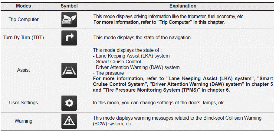
Trip computer mode
The trip computer mode displays information related to vehicle driving parameters including fuel economy, tripmeter information and vehicle speed.
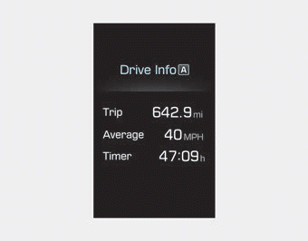
Turn By Turn (TBT) mode
This mode displays the state of the navigation.
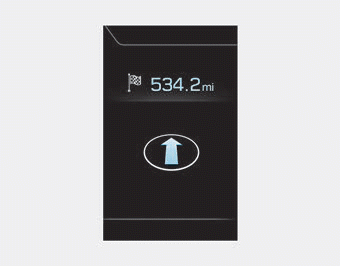
Assist mode
SCC/LKA/DAW (if equipped)
This mode displays the state of the Smart Cruise Control (SCC), Lane Keeping Assist (LKA) system and Driver Attention Warning (DAW) system.
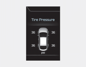
Tire Pressure
This mode displays information related to Tire Pressure.
Warning mode
If one of followings occurs, warning messages will be displayed on the LCD display for several seconds.
- Lower washer fluid (if equipped)
- Exterior lamp malfunction
- Blind-Spot Collision Warning (BCW) system malfunction (if equipped)
- Forward Collision-Avoidance Assist (FCA) malfunction (if equipped)
- High Beam Assist malfunction (if equipped)
- Smart cruise control malfunction
- Tire Pressure Monitoring System (TPMS) malfunction
 User settings mode
In this mode, you can change the settings of the instrument cluster, doors, lamps,
etc.
1. Driver Assistance
2. Door
3. Lights
4. Convenience
5. Service Interval
6...
 User settings mode
In this mode, you can change the settings of the instrument cluster, doors, lamps,
etc.
1. Driver Assistance
2. Door
3. Lights
4. Convenience
5. Service Interval
6...
Other information:
Hyundai Ioniq (AE) 2017-2024 Owner's Manual: Vehicle Stability Management (VSM)
The Vehicle Stability Management (VSM) is a function of the Electronic Stability Control (ESC) system. It helps ensure the vehicle stays stable when accelerating or braking suddenly on wet, slippery and rough roads where traction over the four tires can suddenly become uneven...
Hyundai Ioniq (AE) 2017-2024 Service Manual: DCT Control Module (TCM). Schematic diagrams
1. TCM Connector and Terminal Function2. TCM Terminal FunctionConnector [A] Pin Description Pin Description 1Clutch Actuator (Clutch Motor 1 (ODD)_Phase V)17-2Clutch actuator (Clutch Motor 2 (EVEN) Phase V)18Clutch Actuator (Clutch Motor 1 (ODD)_HALL 1)3Select Actuator (Select Solenoid 2 (EVEN)_Ground)19Clutch Actuator (Clutch Motor 1 (ODD)_Sensor Supply)4Select Actuator (Select Solenoid 1 (ODD) Push)20Select Actuator (Select Solenoid 1 (ODD)_Sensor Sensor Supply)5Clutch Actuator (Clutch Motor 1 (ODD)_Phase U)21Select Actuator (Select Solenoid 2 (EVEN)_Sensor Sensor Supply)6Clutch Actuator (Clutch Motor 2 (EVEN)_Phase U)22Select Actuator (Select Solenoid 2 (EVEN)_Sensor Ouput)7Select Actuator (Select Solenoid 1 (ODD)_Ground)23Clutch Actuator (Clutch Motor 2 (EVEN)_HALL 2)8Select Actuator (Select Solenoid 2 (EVEN)_ Pull)24Clutch Actuator (Clutch Motor 2 (EVEN)_HALL 3)9Clutch Actuator (Clutch Motor1 (ODD)_Phase W)25Clutch Actuator (Clutch Motor 2 (EVEN)_Ground)10Clutch Actuator (Clutch Motor 2 (EVEN)_Phase W)26Select Actuator (Select Solenoid 1 (ODD)_Sensor Output)11Select Actuator (Select Solenoid 1 (ODD) Pull)27-12Select Actuator (Select Solenoid 2 (EVEN) Push)28Clutch Actuator (Clutch Motor 2 (EVEN)_HALL 1)13Clutch Actuator (Clutch Motor 1 (ODD)_HALL 2)29Clutch Actuator (Clutch Motor 2 (EVEN)_Sensor Supply)14Clutch Actuator (Clutch Motor (ODD)_HALL 3)30Select Actuator (Select Solenoid 1 (ODD)_Sensor Ground)15Clutch Actuator (Clutch Motor 1 (ODD)_Ground)31Select Actuator (Select Solenoid 2 (EVEN)_Sensor Ground)16-32-Connector [B] Pin Description Pin Description 1-35-2-36-3ON / START Input37-4Paddle Shift (Up) Switch signal38-5Inhibitor Switch "P" Input signal39-6Inhibitor Switch "R" Input signal40-7Inhibitor Switch "D" Input signal41Shift Actuator (Shift Motor 2 (EVEN) _HALL 2)8Sports mode "Down" shift42Shift Actuator (Shift Motor 2 (EVEN) _HALL 3)9Clutch Speed Sensor (EVEN) Ground43Inhibitor Switch "M" Input signal10-44CAN1 Communication Port1 High11-45CAN1 Communication Port1 Low12-46-13Shift Actuator (Shift Motor 1 (ODD) _HALL 2)47-14Shift Actuator (Shift Motor 1 (ODD) _HALL 3)48Flex ray High (BP)15-49Input Speed Sensor Supply 1 (ODD)16-50Input Speed Signal 1 (ODD)17Battery Power Low VBD 51-18Paddle Shift Down signal52-19Shift Lever Select Switch53-20Inhibitor Switch "N" Input signal54Shift Actuator (Shift Motor 2 (EVEN) _Sensor Supply)21Sports mode "Up" shift55Shift Actuator (Shift Motor 2 (EVEN) _HALL 1)22-56Shift Actuator (Shift Motor 2 (EVEN) _Sensor Ground)23Input Speed Sensor Supply 2 (EVEN)57Power Ground 1 for High Current Modules245V spare Sensor Supply output58Power Ground 2 for High Current Modules25-59Shift Actuator (Shift Motor 2 (EVEN)_Phase W)26Shift Actuator (Shift Motor 1 (Odd)_Sensor Supply)60Shift Actuator (Shift Motor 1 (ODD)_Phase W)27Shift Actuator (Shift Motor 1 (ODD)_HALL 1)61 Power Ground 3 for High Current Modules28Select Actuator (Shift Motor 1 (ODD)_Sensor Ground)62-29-63Shift Actuator (Shift Motor 2 (EVEN)_Phase V)30CAN2 Communication Port2 High64Shift Actuator (Shift Motor 1 (ODD)_Phase V)31CAN2 Communication Port2 Low65Motor Sensor Supply Voltage 1 from Direct Battery32-66Motor Sensor Supply Voltage 2 from Direct Battery33-67Shift Actuator (Shift Motor 2 (EVEN)_Phase U)34Flex ray bus, BM68Shift Actuator (Shift Motor 1 (ODD)_Phase U)3...
Categories
- Manuals Home
- 1st Generation Ioniq Owners Manual
- 1st Generation Ioniq Service Manual
- Washer Fluid
- Hybrid battery SOC (State of Charge) gauge
- If the 12 Volt Battery is Discharged (Hybrid Vehicle)
- New on site
- Most important about car
Seatback pocket
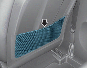
The seatback pocket is provided on the back of the front passenger's seatback.
WARNING
To prevent the Occupant Classification System from malfunctioning:
