Hyundai Ioniq (AE): Power Door Mirrors / Power Door Mirror Switch. Repair procedures
| Inspection |
| 1. | Disconnect the negative (-) battery terminal. |
| 2. | Remove the driver door trim. (Refer to Body - "Front Door Trim") |
| 3. | Disconnect the power mirror switch connector from the door trim.
|
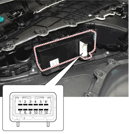
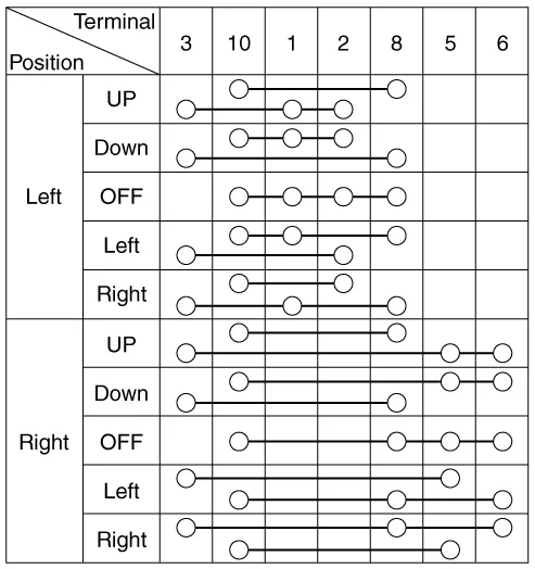
| 4. | Check for continuity between the terminals in each switch position according to the table. [Power Mirror Switch]
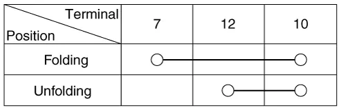
[Power Folding Mirror Switch]
|
| Removal |
| 1. | Disconnect the negative (-) battery terminal. |
| 2. | Remove the front door trim. (Refer to Body - "Front Door Trim") |
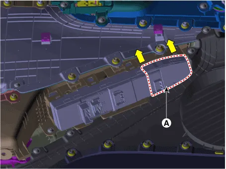
| 3. | Remove the power window assembly (A).
|
| Installation |
| 1. | Install the power window switch assembly. |
| 2. | Install the front door trim after connect the connector. |
| 3. | Connect the negative (-) battery terminal.
|

Circuit Diagram
Removal1.Disconnect (-) battery terminal.2.Using a fastener remover (C), remove the mirror (A) as illustration below. • Protect mirror from removing tool with cloth (B) wrapped.
Other information:
Hyundai Ioniq (AE) 2017-2022 Service & Repair Manual: Heater Unit. Components and components location
Component Location1. Heater unit assemblyCompoents1. Heater core cover2. Heater core & Seal assembly3. Mode actuator [LH]4. Temperature control actuator [LH]5. Shower duct [LH]6. Duct sensor [Floor]7. PTC Heater8. Duct sensor [Vent]9. Heater & Evaporator lower case10.
Hyundai Ioniq (AE) 2017-2022 Service & Repair Manual: Mode Control Actuator. Repair procedures
Inspection1.Turn the ignition switch OFF.2.Disconnect the mode control actuator connector.3.Verify that the mode control actuator operates to the defrost mode when connecting 12V to terminal 3 and grounding terminal 4.Verify that the mode control actuator operates to the vent mode when connected in reverse.
Categories
- Manuals Home
- Hyundai Ioniq Owners Manual
- Hyundai Ioniq Service Manual
- Audio
- Jump Starting
- Immobilizer System
- New on site
- Most important about car
