Hyundai Ioniq (AE): Rail Pressure Sensor (RPS) / Schematic diagrams
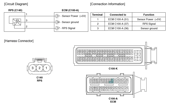
| Circuit Diagram |
Signal Waveform
Inspection1.Connect the GDS on the Data Link Connector (DLC).2.Measure the output voltage of the RPS at idle and various engine speed. Condition Output Voltage (V) Idle Approx.
Other information:
Hyundai Ioniq (AE) 2017-2022 Service & Repair Manual: Blower Unit. Components and components location
Component Location1. Blower unit assembly Components1. Duct Seal2. Intake duct case3. Air intake door assembly4. Intake door5. Seal6. Intake duct case (A)7. Air filter cover (A)8. Intake actuator9. Air filter cover10. Air filter 11. Blower unit pad12.
Hyundai Ioniq (AE) 2017-2022 Service & Repair Manual: Climate Control Air Filter. Repair procedures
Replacement1.Disconnect the air damper (A) from the glove box (B).2.Remove the stopper (B) from the glove box (A).3.Remove the filter cover (A) by pressing the knob.4.Replace the air filter (A) with a new one according to the direction of air filter. • To remove the filter easily, press the right side inwa
Categories
- Manuals Home
- Hyundai Ioniq Owners Manual
- Hyundai Ioniq Service Manual
- Theft-alarm System
- AVN(Audio Video Navigation) head unit. Components and components location
- Jump Starting
- New on site
- Most important about car
