Hyundai Ioniq (AE): Smart Key System / Smart Key Unit. Repair procedures
Hyundai Ioniq (AE) 2017-2022 Service & Repair Manual / Body Electrical System / Smart Key System / Smart Key Unit. Repair procedures
| Removal |
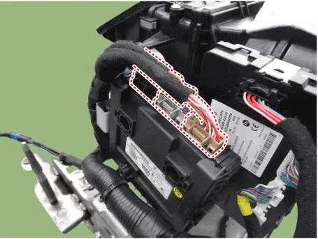
Smart Key Unit
| 1. | Disconnect the negative (-) battery terminal. |
| 2. | Remove the glove box. (Refer to Body - "Glove Box Upper Cover Assembly") |
| 3. | Remove the smart key unit (A) after disconnecting the connectors (B) and loosening the bolt and nut.
|
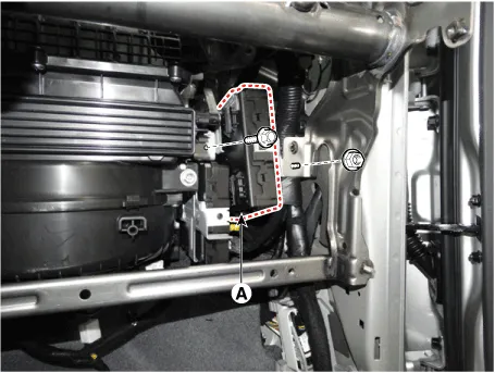
Interior 1 Antenna
|

| 1. | Disconnect the negative (-) battery terminal. |
| 2. | Remove the console upper cover. (Refer to Body - "Floor Console Assembly") |
| 3. | Remove the interior 1 antenna (B) after loosening the mounting nuts and disconnect the connector (A).
|
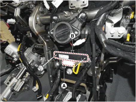
Interior 2 Antenna
| 1. | Disconnect the negative (-) battery terminal. |
| 2. | Remove the console upper cover (Refer to Body - "Floor Console Assembly") |
| 3. | Remove the interior 2 antenna (A) after loosening the mounting nuts (2EA) and disconnecting the connector (B).
|
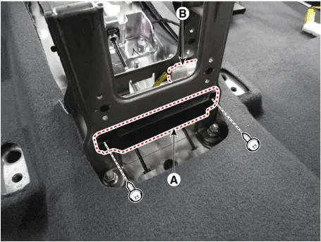
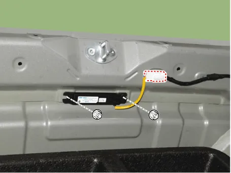
Trunk Antenna
| 1. | Disconnect the negative (-) battery terminal |
| 2. | Remove the rear transverse trim. (Refer to Body - "Trunk Trim") |
| 3. | Remove the trunk antenna (B) after disconnect the connector (A) and loosening the mounting nuts.
|
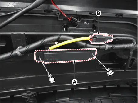
Rear Bumper Antenna
| 1. | Disconnect the negative (-) battery terminal. |
| 2. | Remove the rear bumper cover. (Refer to Body - "Rear Bumper Cover") |
| 3. | Remove the rear bumper antenna (A) after disconnect the connector (B) and loosening the mounting nuts.
|
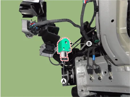
Buzzer
| 1. | Disconnect the negative (-) battery terminal. |
| 2. | Remove the front left wheel guide. (Refer to Body - "Front Wheel Guard") |
| 3. | Remove the buzzer (B) after disconnect the connector (A)
|
Door Outside Handle
| 1. | Disconnect the negative (-) battery terminal. |
| 2. | Remove the front outside door handle. (Refer to Body - "Front Door Outside Handle")
|
| Inspection |
Smart Key Unit
(Refer to Smart Key System - "Smart Key Diagnostic")
Smart Key Switch
(Refer to Smart Key System - "Smart Key Diagnostic")
Antenna
(Refer to Smart Key System - "Smart Key Diagnostic")
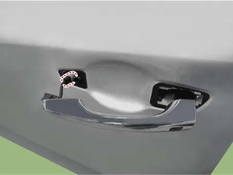
Door Outside Handle
| 1. | Disconnect the front door outside handle connector (A).
|
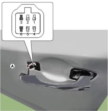
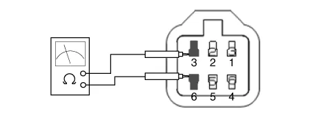
| 2. | Check for continuity between terminals No 3 and No 6.
|

| Installation |
Smart Key Unit
| 1. | Install the smart key unit. |
| 2. | Install the smart key unit mounting bolts and connect the connector. |
| 3. | Install the glove box. |
| 4. | Install the negative (-) battery terminal and check the smart key system. |
Interior 1 Antenna
| 1. | Install the interior 1 antenna. |
| 2. | Install the crash pad center panel. |
| 3. | Install the negative (-) battery terminal and check the smart key system. |
Interior 2 Antenna
| 1. | Install the interior 2 antenna. |
| 2. | Install the console rear complete assembly. |
| 3. | Install the negative (-) battery terminal and check the smart key system. |
Trunk Antenna
| 1. | Trunk mounted antenna. |
| 2. | Install the rear transverse trim. |
| 3. | Install the negative (-) battery terminal and check the smart key system. |
Rear Bumper Antenna
| 1. | Install the rear bumper antenna. |
| 2. | Install the rear bumper cover. |
| 3. | Install the negative (-) battery terminal and check the smart key system |
Door Outside Handle
| 1. | Install the outside handle. |
| 2. | Install the front outside door handle. |
| 3. | Install the negative (-) battery terminal and check the smart key system. |
Circuit Diagram
InspectionSelf Diagnosis with Scan ToolIt will be able to diagnose defects of SMART KEY system with GDS quickly. GDS can operates actuator forcefully, input/output value monitoring and self diagnosis.
Other information:
Hyundai Ioniq (AE) 2017-2022 Service & Repair Manual: Smart Cruise Control (SCC) Switch. Components and components location
C
Hyundai Ioniq (AE) 2017-2022 Service & Repair Manual: Troubleshooting
Trouble Symptom ChartsTrouble Symptom 1Trouble Symptom 2 Trouble symptom Probable cause Remedy The set vehicle speed varies greatly upward or downward"Surging" (repeated alternating acceleration and deceleration) occurs after settingMalfunction of the vehicle speed se
Categories
- Manuals Home
- Hyundai Ioniq Owners Manual
- Hyundai Ioniq Service Manual
- Theft-alarm System
- Brake System
- AVN(Audio Video Navigation) head unit. Components and components location
- New on site
- Most important about car

Copyright © 2025 www.hioniqae.com - 0.0131