Hyundai Ioniq (AE): Head Lamp Leveling Device / Head Lamp Leveling Switch. Repair procedures
Hyundai Ioniq (AE) 2017-2022 Service & Repair Manual / Body Electrical System / Head Lamp Leveling Device / Head Lamp Leveling Switch. Repair procedures
| Inspection |
| 1. | Disconnect the negative (-) battery terminal. |
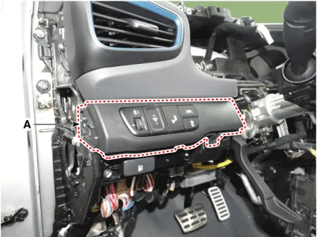
| 2. | Remove the crash pad lower panel (A). (Refer to Body - "Crash Pad Lower Panel")
|
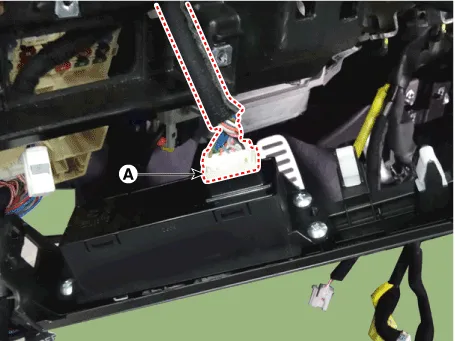
| 3. | Disconnect the rheostat switch connector (A).
|
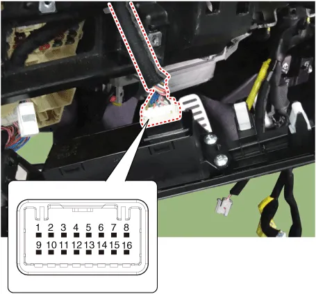
| 4. | Operate the BSD switch, then check for continuity between terminals of BSD switch connector.
|
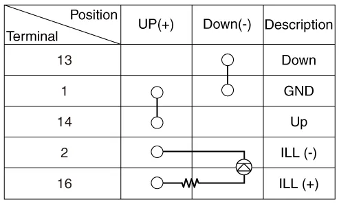
SCHEMATIC DIAGRAM
Other information:
Hyundai Ioniq (AE) 2017-2022 Service & Repair Manual: PTC Heater. Repair procedures
InspectionOperating Logic Test (Manual only)Inspect the PTC operation by confirmation logic as follows.1.Entering(1)Set the Floor mode and maximum heating position.(2)Turn off the blower switch.(3)Press the intake (recirculation) button 5 times or more.
Hyundai Ioniq (AE) 2017-2022 Service & Repair Manual: Mode Control Actuator. Repair procedures
Inspection1.Turn the ignition switch OFF.2.Disconnect the mode control actuator connector.3.Verify that the mode control actuator operates to the defrost mode when connecting 12V to terminal 3 and grounding terminal 4.Verify that the mode control actuator operates to the vent mode when connected in reverse.
Categories
- Manuals Home
- Hyundai Ioniq Owners Manual
- Hyundai Ioniq Service Manual
- Engine Clutch System
- Body (Interior and Exterior)
- Suspension System
- New on site
- Most important about car

Copyright © 2026 www.hioniqae.com - 0.0225