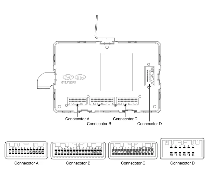
Hyundai Ioniq (AE): BCM (Body Control Module) / Components and components location
| Components |
|
NO
|
Connector A
|
Connector B
|
Connector C
|
Connector D
|
| 1 | - | Key in switch | Wiper low relay | IGN 1 |
| 2 | - | Steering heated switch | Auto light ground | IG2 Steering heated power 1 |
| 3 | Rear left seat belt indicator | - | PAS ON Indicator | IG2 Steering heated power 2 |
| 4 | Passenger seat belt indicator | - | Steering heated indicator | IG2 Steering heated power output |
| 5 | Rear centor seat belt indicator | - | - | Room lamp |
| 6 | Rear right seat belt indicator | - | COM | Ground |
| 7 | - | - | Crash output | Power |
| 8 | - | PAS Input | Crash output | - |
| 9 | Mirror unfolding relay | Key inter lock switch | Auto light sensor | - |
| 10 | - | Sunroof open switch | NTC Sensor | RPAS Power |
| 11 | - | PAS ON Switch | Head lamp switch (High) | FPAS Power |
| 12 | - | Multifunction switch ground | Wiper int vol relay | Ground signal |
| 13 | Key solenoid | - | Front wiper switch | |
| 14 | - | - | foglamp switch | |
| 15 | ATM solenoid output | - | Wiper relay (High) | |
| 16 | - | - | Auto light (Power) | |
| 17 | Security indicator | - | Sunroof enable (High) | |
| 18 | Poket lamp output | - | - | |
| 19 | Safety powerwindow down (Low) | C-Can (Low) | - | |
| 20 | Key hole illumination | C-Can (High) | - | |
| 21 | - | B-CAN (Low) | Front wiper low backup switch | |
| 22 | - | B-CAN (High) | NTC Ground | |
| 23 | Mirror folding relay output | - | IGN 1 | |
| 24 | - | - | ACC | |
| 25 | PAS | - | ||
| 26 | - | Front wiper washer switch | ||
| 27 | - | Blade position | ||
| 28 | Defogger switch | Brake switch | ||
| 29 | - | |||
| 30 | - | |||
| 31 | - | |||
| 32 | - |
Specifications Items Specifications Rated voltageDC 12VOperating voltageDC 9 - 16VOperating temperature-22°F to 167°F (-30°C to 75°C)Dark currentSMK : 3mA / Keyless : 4mA
Circuit Diagram
Other information:
Hyundai Ioniq (AE) 2017-2022 Service & Repair Manual: Auto Defogging Sensor. Description and operation
DescriptionThe auto defogging sensor is installed on the front window glass. The sensor judges and sends signal if moisture occurs to blow out wind for defogging. The air conditioner control module receives signal from the sensor and restrains moisture and eliminate defog by controlling the intake actuator, A/C, auto defogging actuator, blower moto
Hyundai Ioniq (AE) 2017-2022 Service & Repair Manual: Auto Defoging Actuator. Repair procedures
Inspection1.Turn the ignition switch OFF. 2.Disconnect the auto defogging connector. 3.Verify that the auto defogging actuator operates to the open position when connecting 12V to terminal 3 and grounding terminal 4. Verify that the auto defogging actuator operates to the close position when connected in reverse.
Categories
- Manuals Home
- Hyundai Ioniq Owners Manual
- Hyundai Ioniq Service Manual
- Checking the Coolant Level
- Maintenance
- Engine Clutch System
- New on site
- Most important about car
