Hyundai Ioniq (AE): BCM (Body Control Module) / Schematic diagrams
| Circuit Diagram |
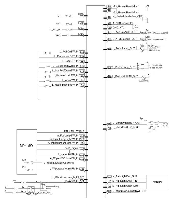
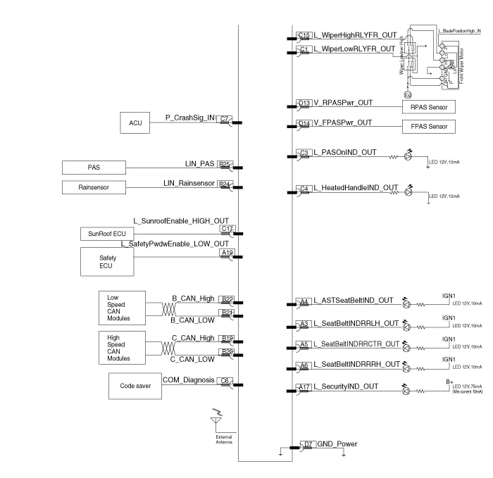
Components NO Connector A Connector B Connector C Connector D 1-Key in switchWiper low relayIGN 1 2-Steering heated switchAuto light groundIG2 Steering heated power 13Rear left seat belt indicator-PAS ON IndicatorIG2 Steering heated power 24Passenger seat belt indicator-Steering heated indicatorIG2 Steering heated power output5Rear centor seat belt indicator--Room lamp6Rear right seat belt indicator-COMGround7--Crash outputPower8-PAS InputCrash output-9Mirror unfolding relayKey inter lock switchAuto light sensor-10-Sunroof open switch NTC SensorRPAS Power11-PAS ON SwitchHead lamp switch (High)FPAS Power12-Multifunction switch groundWiper int vol relayGround signal13Key solenoid-Front wiper switch14--foglamp switch15ATM solenoid output-Wiper relay (High)16--Auto light (Power)17Security indicator-Sunroof enable (High)18Poket lamp output--19Safety powerwindow down (Low)C-Can (Low)-20Key hole illuminationC-Can (High)-21-B-CAN (Low)Front wiper low backupswitch22-B-CAN (High)NTC Ground23 Mirror folding relay output-IGN 124--ACC25PAS-26-Front wiper washer switch27-Blade position28Defogger switchBrake switch29-30-31-32-
DescriptionBody Control Module (BCM) function No Item Description 1Washer Linked Wiper– If the washer switch is pressed ON for 0.
Other information:
Hyundai Ioniq (AE) 2017-2022 Service & Repair Manual: Front Radar Unit. Description and operation
DescriptionThe smart cruise control unit is installed on the front right side of the chassis. A radar sensor is embedded in the front section of the unit. This sensor detects vehicles and objects in front of the vehicle. The radar sensor can detect up to 64 objects ahead of a vehicle.
Hyundai Ioniq (AE) 2017-2022 Service & Repair Manual: Description and operation
DescriptionRear view monitor (RVM) will activate when the backup light is ON with the ignition switch ON and the shift lever in the R position.This system is a supplemental system that shows behind the vehicle through the AV monitor while backing-up. • This system is a supplementary function only.
Categories
- Manuals Home
- Hyundai Ioniq Owners Manual
- Hyundai Ioniq Service Manual
- Heating, Ventilation and Air Conditioning
- Transmission Gear Oil. Repair procedures
- How to Connect Portable Charger (ICCB: In-Cable Control Box)
- New on site
- Most important about car
