Hyundai Ioniq (AE): Cruise Control System / Cruise Control Switch. Schematic diagrams
Hyundai Ioniq (AE) 2017-2022 Service & Repair Manual / Advanced Driver Assistance System (ADAS) / Cruise Control System / Cruise Control Switch. Schematic diagrams
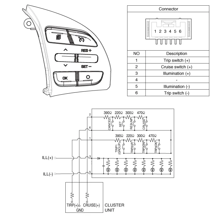
| Circuit Diagram |
Component Location1. Audio switch (LH)2. Cruise switch (RH)
Removal1.Disconnect the negative (-) battery terminal.2.Remove the steering wheel assembly.(Refer to Steering System - "Steering Wheel")3.Remove the steering back cover (A).
Other information:
Hyundai Ioniq (AE) 2017-2022 Service & Repair Manual: Ambient Temperature Sensor. Components and components location
C
Hyundai Ioniq (AE) 2017-2022 Service & Repair Manual: Auto Defoging Actuator. Description and operation
DescriptionThe auto defogging sensor is installed on front window glass. The sensor judges and sends signal if moisture occurs to blow out wind for defogging. The air conditioner control module receives a signal from the sensor and restrains moisture and eliminates defog by the intake actuator, A/C, auto defogging actuator, blower motor rpm and mod
Categories
- Manuals Home
- Hyundai Ioniq Owners Manual
- Hyundai Ioniq Service Manual
- Jump Starting
- Brake System
- Jump starting procedure
- New on site
- Most important about car

Copyright © 2026 www.hioniqae.com - 0.0144