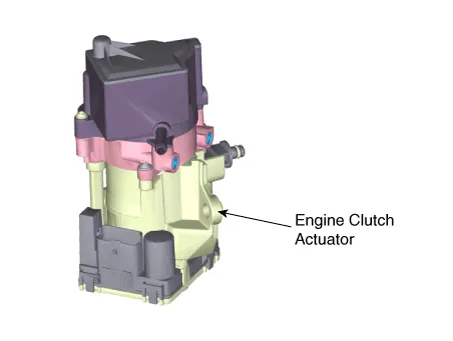
| 2. | After replacing the Engine clutch actuator, operate the followings in order using GDS equipment. | (1) | Engine clutch inspection line learning and diagnostic information. 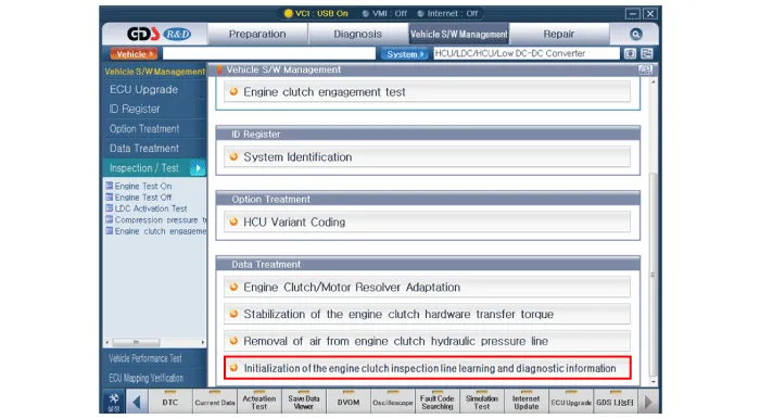
|
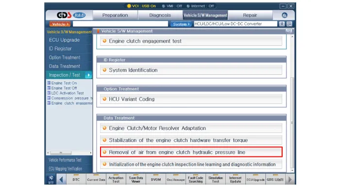
| (2) | Removal of air from engine clutch hydraulic pressure line. | •
| When using a vacuum-pressure equipment to inject hydraulic fluid, the vacuum pressure should be no more than 2.5 torr and the injection pressure should be between 2.3 - 2.5 bars. |
| •
| If it is impossible to inject hydraulic fluid using the above condition, be sure to remove air from the hydraulic line of the engine clutch at a temperature between 0 - 40°C. |
|
|
| (3) | Engine clutch/motor resolver adaptation. 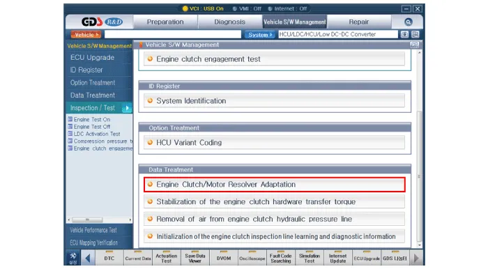
|
| (4) | Stabilization of the engine clutch hardware transfer torque. 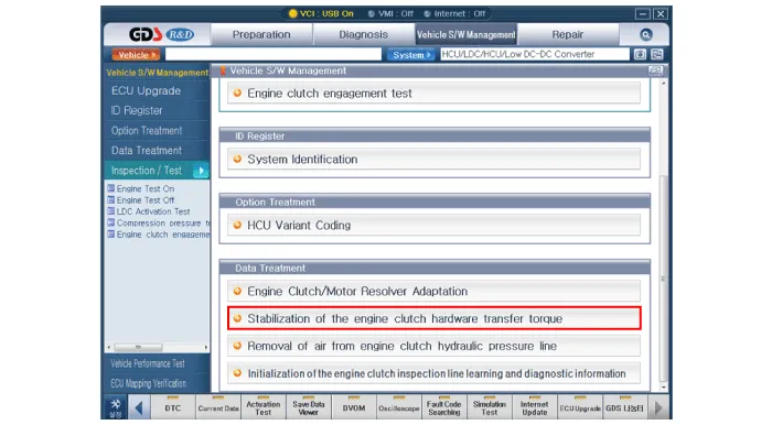
|
|