Hyundai Ioniq (AE): Air Conditioning System / Evaporator Temperature Sensor. Repair procedures
| Inspection |
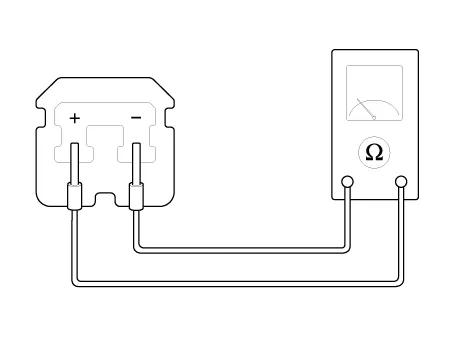
| 1. | Turn the ignition switch OFF. |
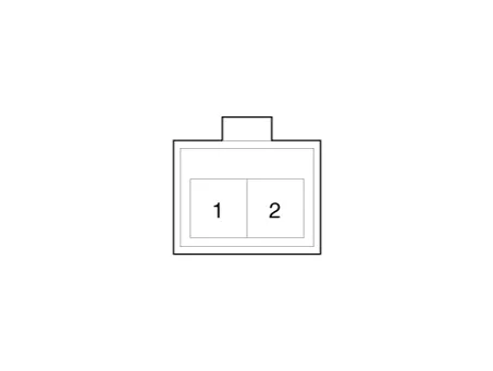
| 2. | Disconnect the evaporator temperature sensor connector. |
| 3. | Measure the resistance between terminal "+" and "-" of the evaporator temperature sensor.
Specification
|
| Diagnosis With GDS |
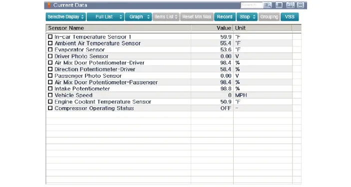
| 1. | The heating, ventilation and air conditioning can be quickly diagnosed failed parts with vehicle diagnostic system (GDS). ※ The diagnostic system (GDS) provides the following information. (1) Self diagnosis : Checking the failure code (DTC) and display. (2) Current data : Checking the system input/output data state. (3) Actuation test : Checking the system operation condition. (4) Additional function : Other controlling such as he system option and zero point adjustment. |
| 2. | Select the 'Car model' and the system to be checked in order to check the vehicle with the tester. |
| 3. | Select the 'Current data' menu to search the current state of the input / output data. The input/output data for the sensors corresponding to the Evaporator Temperature Sensor can be checked.
|
| Replacement |
| 1. | Disconnect the negative (-) battery terminal. |
| 2. | Remove the heater and blower assembly. (Refer to Heater - "Heater Unit") |
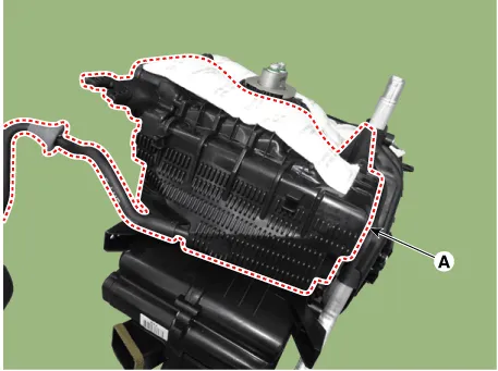
| 3. | Remove the evaporator core cover (A) after loosening the mounting screws.
|
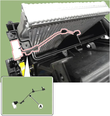
| 4. | Pull out the evaporator temperature sensor (A) from the evaporator core.
|
| 5. | To install, reverse the removal procedure.
|


DescriptionThe evaporator temperature sensor will detect the evaporator core temperature and interrupt compressor relay power in order to prevent evaporator from freezing by excessive cooling.
DescriptionThe In-car air temperature sensor is built in the heater & A/C control unit.The sensor contains a thermistor which measures the temperature of the inside.
Other information:
Hyundai Ioniq (AE) 2017-2022 Service & Repair Manual: Auto Defogging Sensor. Repair procedures
Diagnosis With GDS1.The heating, ventilation and air conditioning can be quickly diagnosed failed parts with vehicle diagnostic system (GDS).※ The diagnostic system (GDS) provides the following information.(1) Self diagnosis : Checking the failure code (DTC) and display.
Hyundai Ioniq (AE) 2017-2022 Service & Repair Manual: Description and operation
DescriptionRear corner radar is a system that uses two magnetic wave radar sensors attached on the rear panel to measure the distance from the following vehicles and provides the sensing and (visual and auditory) alarm of any vehicle coming into the blind spot.
Categories
- Manuals Home
- Hyundai Ioniq Owners Manual
- Hyundai Ioniq Service Manual
- Checking the Coolant Level
- If the 12 Volt Battery is Discharged (Hybrid Vehicle)
- Suspension System
- New on site
- Most important about car
