Hyundai Ioniq (AE): Air Conditioning System / In-car Sensor. Repair procedures
| Diagnosis With GDS |
| 1. | The heating, ventilation and air conditioning can be quickly diagnosed failed parts with vehicle diagnostic system (GDS). ※ The diagnostic system (GDS) provides the following information. (1) Self diagnosis : Checking the failure code (DTC) and display. (2) Current data : Checking the system input/output data state. (3) Actuation test : Checking the system operation condition. (4) Additional function : Other controlling such as he system option and zero point adjustment. |
| 2. | Select the 'Car model' and the system to be checked in order to check the vehicle with the tester. |
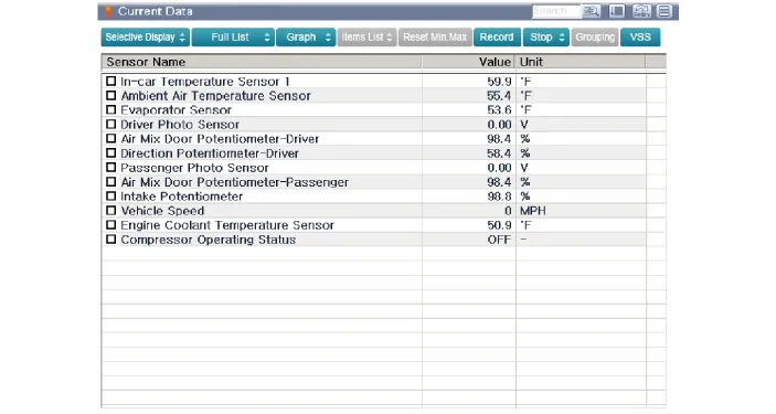
| 3. | Select the 'Current data' menu to search the current state of the input / output data. The input / output data for the sensors corresponding to the In-car Sensor can be checked.
|
DescriptionThe In-car air temperature sensor is built in the heater & A/C control unit.The sensor contains a thermistor which measures the temperature of the inside.
Description The photo sensor is located at the center of the defrost nozzles.The photo sensor contains a photovoltaic (sensitive to sunlight) diode. The solar radiation received by its light receiving portion, generates an electromotive force in proportion to the amount of radiation received which is transferred to the automatic temperature control module so that the solar radiation compensation will be performed.
Other information:
Hyundai Ioniq (AE) 2017-2022 Service & Repair Manual: Receiver-Drier. Repair procedures
Replacement1.Remove the condenser.2.Remove the cap (A) on the bottom of the condenser with a L wrench. Tightening torque : 9.81 - 14.71 N.m (1.0 - 1.5 kgf.m, 7.2 - 10.8 lb-ft) 3.Remove the receiver-drier (A) from condenser using a long nose plier.
Hyundai Ioniq (AE) 2017-2022 Service & Repair Manual: Smart Cruise Control (SCC) Switch. Repair procedures
Removal1.Disconnect the negative (-) battery terminal.2.Remove the steering wheel assembly.(Refer to Steering System -"Steering Wheel")3.Remove the steering back cover (A).4.Remove the steering remote control connector (A).5.Remove the steering remote control (A), after loosening the screws.
Categories
- Manuals Home
- Hyundai Ioniq Owners Manual
- Hyundai Ioniq Service Manual
- Suspension System
- Engine Mechanical System
- Jump starting procedure
- New on site
- Most important about car
