Hyundai Ioniq (AE): IMS(Integrated Memory System) / Memory power seat switch. Repair procedures
Hyundai Ioniq (AE) 2017-2022 Service & Repair Manual / Body Electrical System / IMS(Integrated Memory System) / Memory power seat switch. Repair procedures
| Removal |
| 1. | Disconnect the negative (-) battery terminal. |
| 2. | Remove the driver door trim. (Refer to Body - "Front Door Trim") |
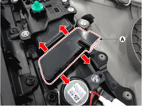
| 3. | Disconnect the memory power seat switch connector (A).
|

| 4. | Remove the memory power switch (A) after disengaging the mounting clips.
|
| Installation |
| 1. | Install the memory power seat control switch (IMS). |
| 2. | Install the door trim. |
| 3. | Connect the negative (-) battery terminal. |
| Inspection |
| 1. | Remove the memory power seat connector
|
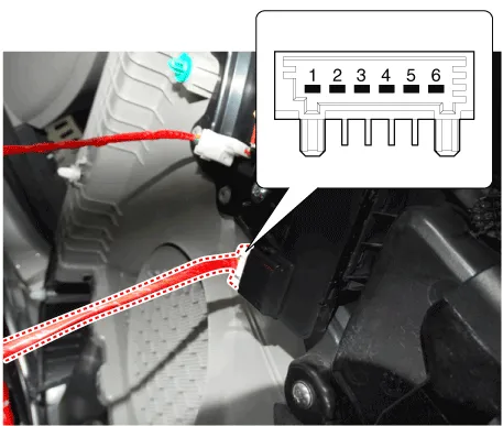
| 2. | When each switch is pressed, check the electricity flow between memory power seat switch connector and grounding, and if the electricity does not match the specification, replace the switch.
|

Other information:
Hyundai Ioniq (AE) 2017-2022 Service & Repair Manual: PTC Heater. Repair procedures
InspectionOperating Logic Test (Manual only)Inspect the PTC operation by confirmation logic as follows.1.Entering(1)Set the Floor mode and maximum heating position.(2)Turn off the blower switch.(3)Press the intake (recirculation) button 5 times or more.
Hyundai Ioniq (AE) 2017-2022 Service & Repair Manual: Repair procedures
Replacement1.Remove the battery (-) terminal.2.Remove the engine room under cover.(Refer to Engine Mechanical System - "Engine Room Under Cover")3.Remove the heater hose (A) and AEWP hose (B).4.Disconnect the lock pin to remove the heater hose pump connector (A).
Categories
- Manuals Home
- Hyundai Ioniq Owners Manual
- Hyundai Ioniq Service Manual
- Suspension System
- Engine Control/Fuel System
- Repair procedures
- New on site
- Most important about car

Copyright © 2026 www.hioniqae.com - 0.018