Hyundai Ioniq (AE): Air Conditioning System / Photo Sensor. Repair procedures
| Inspection |
| 1. | Turn the ignition switch ON. |
| 2. | Connect the GDS. |
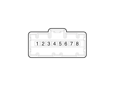
| 3. | Emit intensive light toward the photo sensor using a lamp, and check the output voltage change. |
| 4. | The voltage will rise with higher intensive light and reduce with lower intensive light.
|
| Replacement |
| 1. | Disconnect the negative (-) battery terminal. |
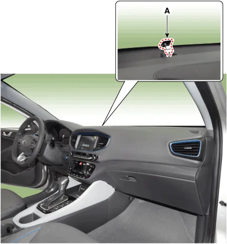
| 2. | Using a screwdriver or remover, remove the photo sensor (A).
|
| 3. | To install, reverse the removal procedure. |
Description The photo sensor is located at the center of the defrost nozzles.The photo sensor contains a photovoltaic (sensitive to sunlight) diode. The solar radiation received by its light receiving portion, generates an electromotive force in proportion to the amount of radiation received which is transferred to the automatic temperature control module so that the solar radiation compensation will be performed.
DescriptionThe ambient temperature sensor is located at the front of the condenser and detects ambient air temperature. It is a negative type thermistor; resistance will increase with lower temperature, and decrease with higher temperature.
Other information:
Hyundai Ioniq (AE) 2017-2022 Service & Repair Manual: Heater Core. Repair procedures
Replacement1.Disconnect the negative (-) battery terminal. 2.Remove the heater and blower assembly.(Refer to Heater - "Heater Unit") 3.Loosen the mounting screws and remove the driver's temperature control actuator (A).4.Remove the heater core cover (A) after loosening the mounting screws.
Hyundai Ioniq (AE) 2017-2022 Service & Repair Manual: Components and components location
C
Categories
- Manuals Home
- Hyundai Ioniq Owners Manual
- Hyundai Ioniq Service Manual
- Checking the Coolant Level
- Transmission Gear Oil. Repair procedures
- Hybrid Control System
- New on site
- Most important about car
