
Hyundai Ioniq (AE): Air Conditioning System / Refrigerant Line. Repair procedures
Hyundai Ioniq (AE) 2017-2022 Service & Repair Manual / Heating, Ventilation and Air Conditioning / Air Conditioning System / Refrigerant Line. Repair procedures
| Replacement |
| 1. | If the compressor is marginally operable, run the engine at idle speed, and let the air conditioning work for a few minutes, then shut the engine off. |
| 2. | Disconnect the negative (-) battery terminal. |
| 3. | Recover the refrigerant with a recovery / charging station.
|

| 4. | Remove the engine cover. (Refer to Engine Mechanical System - "Engine Cover") |
| 5. | Remove the engine mounting support bracket. (Refer to Engine Mechanical System - "Engine Mounting") |
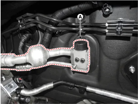
| 6. | Remove the bolts and the expansion valve (A) from the evaporator core.
|
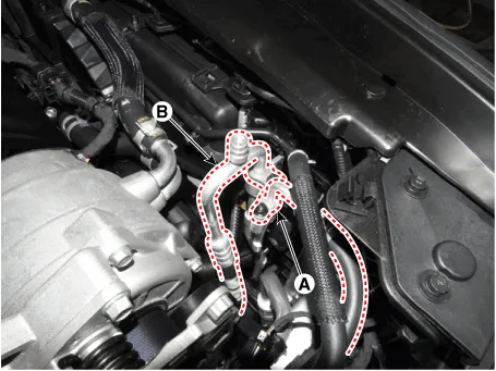
| 7. | Remove the 2 nuts, and then disconnect the discharge line (A) and liquid line (B) from the condenser.
|
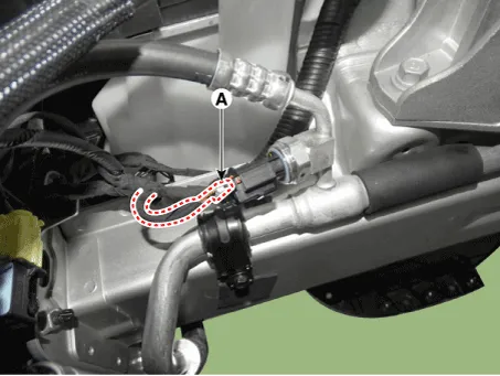
| 8. | Disconnect the A/C pressure transducer connector (A).
|
| 9. | Remove the engine room under cover. (Refer to Engine Mechanical System - "Engine Room Under Cover") |
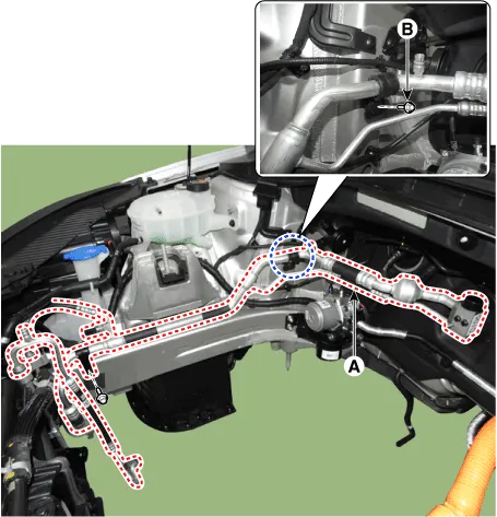
| 10. | Remove the bolts, then disconnect the suction line (A) and discharge line (B) from the compressor.
|


| 11. | Loosen the bracket mounting bolt (B) from suction& liquid assembly (A).
|
| 12. | Remove the refrigerant line assembly (A) to the upper of engine room.
|
| 13. | To install, reverse the removal procedure.
|

Components Location1. Refrigerant Line Assembly
Other information:
Hyundai Ioniq (AE) 2017-2022 Service & Repair Manual: A/C Pressure Transducer. Repair procedures
Inspection • Before measuring the pressure of the refriferant line, check whether the refrigerant amount is charged in accordance with the specified charging amount.(Refer to Heating, Ventilation, Air Conditioning - "Specifications")1.
Hyundai Ioniq (AE) 2017-2022 Service & Repair Manual: Intake Actuator. Components and components location
C
Categories
- Manuals Home
- Hyundai Ioniq Owners Manual
- Hyundai Ioniq Service Manual
- Maintenance
- Engine Mechanical System
- Components and components location
- New on site
- Most important about car

Copyright © 2026 www.hioniqae.com - 0.0197