Hyundai Ioniq (AE): Cruise Control System / Schematic diagrams
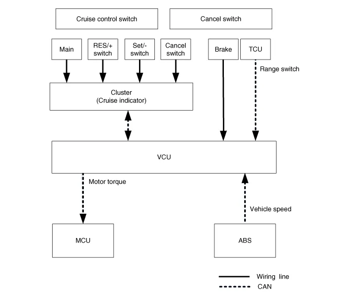
| System Block Diagram |
|
Component part
|
Function
| |
| Vehicle-speed sensor, ESP/ABS Control Module | Converts vehicle speed to pulse. | |
| VCU | Receives signals from sensor and control switches. | |
| Cruise control indicator | Illuminates when CRUISE main switch is ON (Built into cluster) | |
| Cruise Control switches | CRUISE switch | Switch for automatic speed control power supply. |
| Resume/Accel switch (RES +) | Controls automatic speed control functions by Resume/Accel switch (Set/Coast switch) | |
| Set/Coast switch (RES -) | ||
| Cancel switches | Cancel switch | Sends cancel signals to VCU. |
| Brake-pedal switch | ||
| Transaxle range switch (A/T) | ||
| ETC Motor | Regulates the throttle valve to the set opening by ECM. | |
Cruise ControlThe cruise control system is engaged by the cruise "ON/OFF" main switch located on right of steering wheel column. The system has the capability to cruise, coast, accelerate and resume speed.
Trouble Symptom ChartsTrouble Symptom 1Trouble Symptom 2 Trouble symptom Probable cause Remedy The set vehicle speed varies greatly upward or downward"Surging" (repeated alternating acceleration and deceleration) occurs after settingMalfunction of the vehicle speed sensor circuitRepair the vehicle speed sensor system, or replace the partMalfunction of ECMCheck input and output signals at ECMTrouble Symptom 3 Trouble symptom Probable cause Remedy The CC system is not canceled when the brake pedal is depressedDamaged or disconnected wiring of the brake pedal switchRepair the harness or replace the brake pedal switchMalfunction of the ECM signalsCheck input and output signals at ECMTrouble Symptom 4 Trouble symptom Probable cause Remedy The CC system is not canceled when the shift lever is moved to the "N" position (It is canceled, however, when the brake pedal is depressed)Damaged or disconnected wiring of inhibitor switch input circuitRepair the harness or repair or replace the inhibitor switchImproper adjustment of inhibitor switchMalfunction of the ECM signalsCheck input and output signals at ECMTrouble Symptom 5 Trouble symptom Probable cause Remedy Cannot decelerate (coast) by using the "SET/–" switchTemporary damaged or disconnected wiring of "SET/–" switch input circuitRepair the harness or replace the "SET/–" switchMalfunction of the ECM signalsCheck input and output signals at ECMTrouble Symptom 6 Trouble symptom Probable cause Remedy Cannot accelerate or resume speed by using the "RES/+" switchDamaged or disconnected wiring, short circuit or "RES/+" switch input circuitRepair the harness or replace the "RES/+" switchMalfunction of the ECM signalsCheck input and output signals at ECMTrouble Symptom 7 Trouble symptom Probable cause Remedy CC system can be set while driving at a vehicle speed of less than 40km/h (25mph), or there is no automatic cancellation at that speedMalfunction of the vehicle-speed sensor circuitRepair the vehicle speed sensor system, or replace the partMalfunction of the ECM signalsCheck input and output signals at ECMTrouble Symptom 8 Trouble symptom Probable cause Remedy The cruise main switch indicator lamp does not illuminate (But CC system is normal)Damaged or disconnected bulb of cruise main switch indicator lampRepair the harness or replace the part.
Other information:
Hyundai Ioniq (AE) 2017-2022 Service & Repair Manual: Heater Core. Repair procedures
Replacement1.Disconnect the negative (-) battery terminal. 2.Remove the heater and blower assembly.(Refer to Heater - "Heater Unit") 3.Loosen the mounting screws and remove the driver's temperature control actuator (A).4.Remove the heater core cover (A) after loosening the mounting screws.
Hyundai Ioniq (AE) 2017-2022 Service & Repair Manual: emperature Control Actuator. Components and components location
C
Categories
- Manuals Home
- Hyundai Ioniq Owners Manual
- Hyundai Ioniq Service Manual
- Engine Control/Fuel System
- Checking the Coolant Level
- Engine Mechanical System
- New on site
- Most important about car
