Hyundai Ioniq (AE): Air Conditioning System / Ambient Temperature Sensor. Repair procedures
| Inspection |
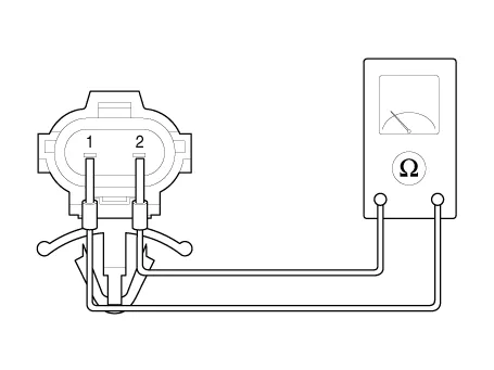
| 1. | Check the resistance of the ambient temperature sensor between terminals 1 and 2 whether it changes by changing the ambient temperature.
Specification
|
| Diagnosis With GDS |
| 1. | The heating, ventilation and air conditioning can be quickly diagnosed failed parts with vehicle diagnostic system (GDS). ※ The diagnostic system (GDS) provides the following information. (1) Self diagnosis : Checking the failure code (DTC) and display. (2) Current data : Checking the system input/output data state. (3) Actuation test : Checking the system operation condition. (4) Additional function : Other controlling such as he system option and zero point adjustment. |
| 2. | Select the 'Car model' and the system to be checked in order to check the vehicle with the tester. |
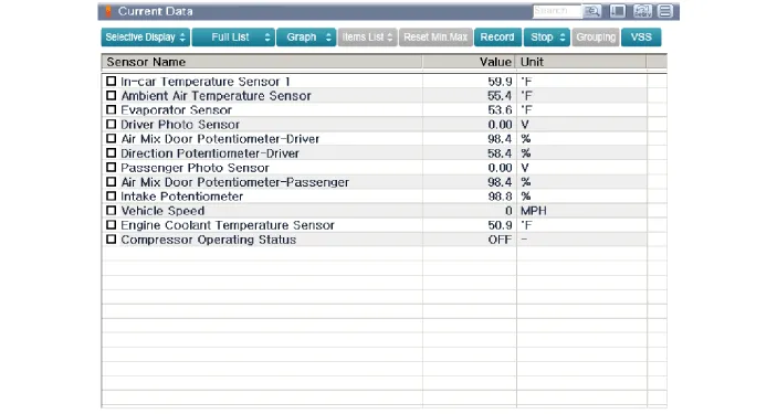
| 3. | Select the 'Current data' menu to search the current state of the input / output data. The input / output data for the sensors corresponding to the Ambient Temperature Sensor can be checked.
|
| Replacement |
| 1. | Disconnect the negative (-) battery terminal. |
| 2. | Remove the front bumper. (Refer to Body - "Front Bumper Cover") |
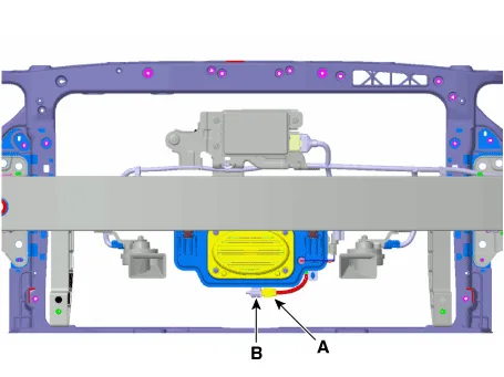
| 3. | Disconnect the connector (A) and then remove the ambient temperature sensor (B).
|
| 4. | To install, reverse the removal procedure. |
Components Location1. Ambient temperature sensor
DescriptionThe auto defogging sensor is installed on the front window glass. The sensor judges and sends signal if moisture occurs to blow out wind for defogging.
Other information:
Hyundai Ioniq (AE) 2017-2022 Service & Repair Manual: A/C Pressure Transducer. Description and operation
DescriptionThe A/C Pressure Transducer (APT) converts the pressure value of high pressure line into voltage value after measuring it. By converted voltage value, engine ECU controls the cooling fan by operating it high speed or low speed. Engine ECU stops the operation of the compressor when the temperature of refrigerant line is very high or very
Hyundai Ioniq (AE) 2017-2022 Service & Repair Manual: Blower Unit. Repair procedures
Replacement When prying with a flat-tip screwdriver or use a prying trim tool, wrap it with protective tape, and apply protective tape around the related parts, to prevent damage.1.Disconnect the negative (-) battery terminal.2.Recover the refrigerant with a recovery / recycling / charging station.
Categories
- Manuals Home
- Hyundai Ioniq Owners Manual
- Hyundai Ioniq Service Manual
- Engine Mechanical System
- Hybrid Vehicle Engine Compartment
- Engine Control/Fuel System
- New on site
- Most important about car
