Hyundai Ioniq (AE): Blower / Blower Unit. Repair procedures
Hyundai Ioniq (AE) 2017-2022 Service & Repair Manual / Heating, Ventilation and Air Conditioning / Blower / Blower Unit. Repair procedures
| Replacement |
When prying with a flat-tip screwdriver or use a prying trim tool, wrap it with protective tape, and apply protective tape around the related parts, to prevent damage. |

| 1. | Disconnect the negative (-) battery terminal. |
| 2. | Recover the refrigerant with a recovery / recycling / charging station.
|

| 3. | When the engine is cool, drain the engine coolant from the radiator. (Refer to Engine Mechanical System - "Coolant") |
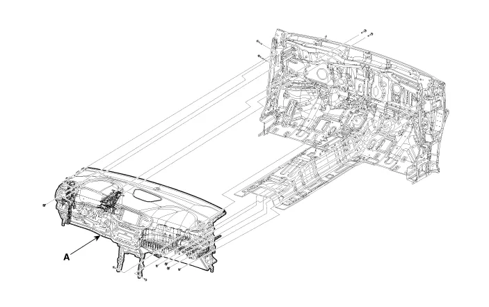
| 4. | Remove the cowl top cover. (Refer to Body - "Cowl Top Cover") |
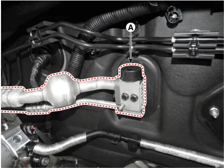
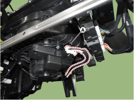
| 5. | Remove the bolts and the expansion valve (A) from the evaporator core.
|

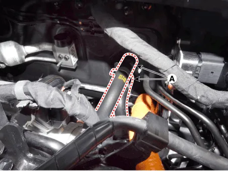
| 6. | Disconnect the heater hoses (A) from the heater unit.
|
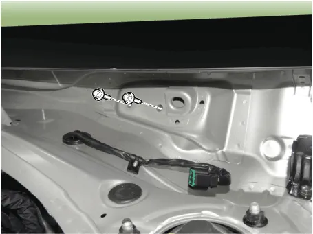
| 7. | Loosen the cowl cross member mounting bolts.
|
| 8. | Remove the floor console assembly. (Refer to Body - "Floor Console Assembly") |
| 9. | Remove the crash pad lower panel. (Refer to Body - "Crash Pad Lower Panel") |
| 10. | Remove both sides of the front pillar trim. (Refer to Body - "Front Pillar Trim") |
| 11. | Remove the cowl side trim. (Refer to Body - "Cowl Side Trim") |
| 12. | Remove the steering column shroud lower panel. (Refer to Body - "Steering Column Shroud Panel") |
| 13. | Remove the steering wheel. (Refer to Steering System - "Steering Wheel") |
| 14. | Remove the multifunction switch. (Refer to Body Electrical System - "Multifunction Switch") |
| 15. | Lower the steering column after loosening the mounting bolts. (Refer to Steering System - "Steering Column and Shaft") |
| 16. | Remove the shift lever assembly. (Refer to Automatic Transmission System - "Shift Lever") |
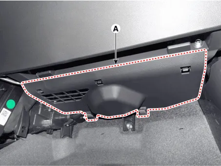
| 17. | Remove the crash pad under cover [RH](A).
|
| 18. | Remove the rear air duct (A).
|

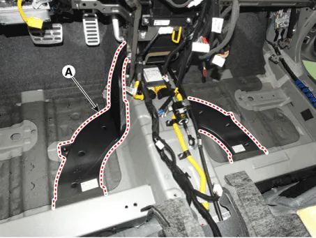
| 19. | Separate the floor carpet (A) to obtain space for removing the rear heating duct.
|

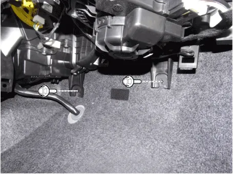
| 20. | Loosen the mounting nuts and remove the front air duct (A).
|
| 21. | Disconnect the airbag control module (SRSCM) connector (A).
|
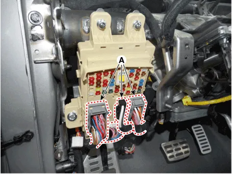
| 22. | Disconnect the junction box connectors (A).
|
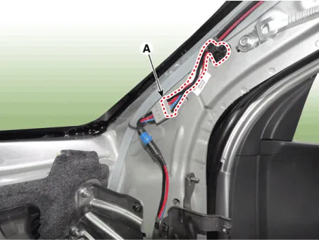
| 23. | Disconnect the multi box connectors (A). [Driver's side]
[Passenger's side]
|
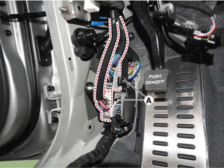
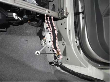
| 24. | Disconnect the connectors (A) and the mounting clips in the front pillar. [Driver's side]
[Passenger's side]
|

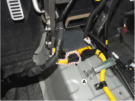
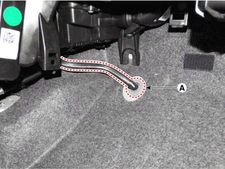
| 25. | Remove the drain hose (A).
|
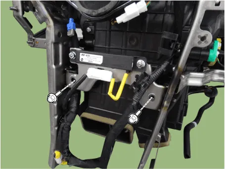
| 26. | Loosen the cowl blower unit mounting bolts.
|
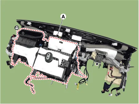
| 27. | After loosening the bolts and nuts remove the main crash pad and cowl cross bar assembly (A) together.
|
| 28. | Disconnect the heater & blower unit connectors.
|
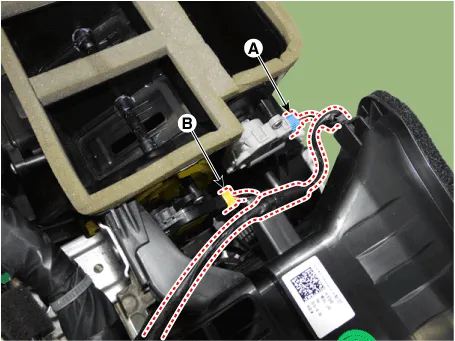
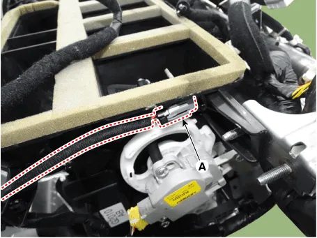
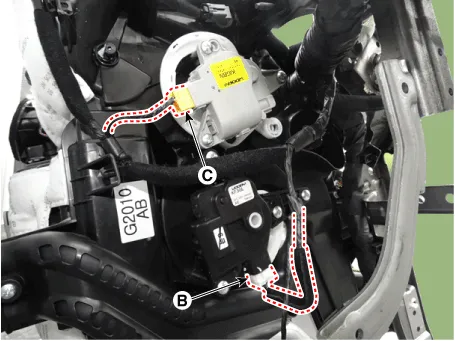
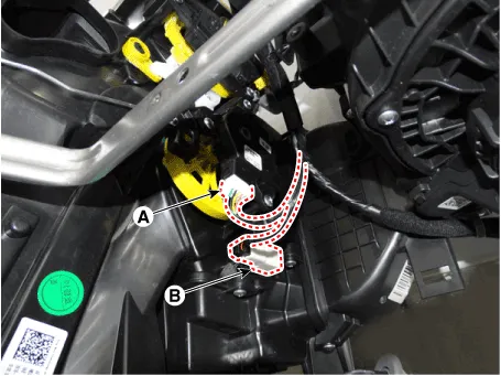

| 29. | Loosen the heater & blower unit mounting bolt (A).
|
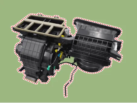
| 30. | Remove the heater and blower unit (A) from the crash pad after loosening the mounting nuts.
|
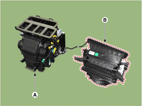
| 31. | Separate the blower unit (B) from the heater unit (A) after loosening the screws.
|
| 32. | To install, reverse the removal procedure. |
Component Location1. Blower unit assembly Components1. Duct Seal2. Intake duct case3. Air intake door assembly4. Intake door5. Seal6. Intake duct case (A)7.
Inspection1.Connect the battery voltage and check the blower motor rotation.2.If the blower motor does not operate well, substitute with a known-good blower motor and check for proper operation.
Other information:
Hyundai Ioniq (AE) 2017-2022 Service & Repair Manual: emperature Control Actuator. Description and operation
DescriptionThe temperature control actuator is located at the heater unit. It regulates the temperature by the procedure as follows. The signal from the control unit adjusts the position of the temperature door by operating the temperature switch. Then the temperature will be regulated by the hot/cold air ratio decided by the position of the temper
Hyundai Ioniq (AE) 2017-2022 Service & Repair Manual: Intake Actuator. Specifications
S
Categories
- Manuals Home
- Hyundai Ioniq Owners Manual
- Hyundai Ioniq Service Manual
- Engine Clutch System
- Repair procedures
- If the 12 Volt Battery is Discharged (Hybrid Vehicle)
- New on site
- Most important about car

Copyright © 2026 www.hioniqae.com - 0.0216