Hyundai Ioniq (AE): Smart Key System / Smart Key Unit. Schematic diagrams
| Circuit Diagram |
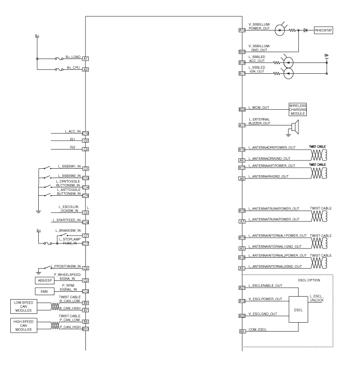
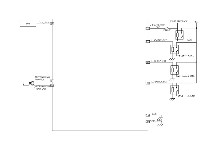
Components (1) No Connector A Connector B Connector C 1Battery (+)_LOADIGN2 Relay outputImmobilizer antenna power input2Battery (+)_CPUIGN1 Relay outputWheel speed signal input3Antenna ground (Internal1)-SSB Switch1 signal input4---5Antenna ground (Internal2)B-CAN (Low)ESCL Unlock switch signal input6Antenna ground (Assist)EMS CANP Position switch signal input7Antenna ground (Trunk)B-CAN (High)Brake switch signal input8Antenna ground (Driver)B-CAN (Low)Ignition 2 signal input9-P-CAN (Low)Ignition 1 signal input10SSB Illumination power (Output)P-CAN (High)Starter relay output11External buzzer output-Immoblizer antenna ground12ESCL Power outputACC Relay outputRPM Signal input13--SSB Switch2 signal input14Antenna power (Internal1)Signal groundDriver toggle button switch signal input15--Assiste toggle button switch signal input16Antenna power (Internal2)SSB ACC LED OutputStarter relay feedback signal input17Antenna power (Assist)SSB IGN LED Output Stop lamp fuse signal input18Antenna power (Trunk)-ACC Signal input19Antenna power (Driver)--20-SSB Illumination groundPower ground21ESCL Enable output-22ESCL Ground outputWireless charging module output
RemovalSmart Key Unit1.Disconnect the negative (-) battery terminal.2.Remove the glove box.(Refer to Body - "Glove Box Upper Cover Assembly")3.Remove the smart key unit (A) after disconnecting the connectors (B) and loosening the bolt and nut.
Other information:
Hyundai Ioniq (AE) 2017-2022 Service & Repair Manual: Intake Actuator. Repair procedures
Inspection1.Turn the ignition switch OFF.2.Disconnect the intake actuator connector.3.Verify that the intake actuator operates to the fresh position when connecting 12V to terminal 3 and grounding terminal 4.Verify that the intake actuator operates to the recirculation position when connected in reverse.
Hyundai Ioniq (AE) 2017-2022 Service & Repair Manual: Repair procedures
Self Diagnosis1.Self-diagnosis process. • When operating the self-diagnostics, the below fault (self-diagnostics code) will blink at 0.5 seconds interval on the temperature display settings (driver's side only) and the remaining symbols are OFF .
Categories
- Manuals Home
- Hyundai Ioniq Owners Manual
- Hyundai Ioniq Service Manual
- Engine Clutch System
- Front Disc Brake. Repair procedures
- Description and operation
- New on site
- Most important about car
