Hyundai Ioniq (AE): Smart Key System / Smart Key Unit. Repair procedures
| Removal |
| 1. | Disconnect the negative (-) battery terminal. |
| 2. | Remove the glove box. (Refer to Body - "Glove Box Upper Cover Assembly") |
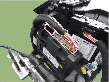
| 3. | Remove the smart key unit (A) after disconnecting the connectors (B) and loosening the bolt and nut.
|
|

| 1. | Disconnect the negative (-) battery terminal. |
| 2. | Remove the console upper cover. (Refer to Body - "Floor Console Assembly") |
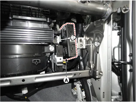
| 3. | Remove the interior 1 antenna (B) after loosening the mounting nuts and disconnect the connector (A).
|
| 1. | Disconnect the negative (-) battery terminal. |
| 2. | Remove the console upper cover (Refer to Body - "Floor Console Assembly") |
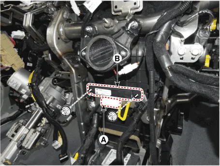
| 3. | Remove the interior 2 antenna (A) after loosening the mounting nuts (2EA) and disconnecting the connector (B).
|
| 1. | Disconnect the negative (-) battery terminal |
| 2. | Remove the rear transverse trim. (Refer to Body - "Trunk Trim") |
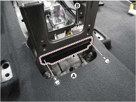
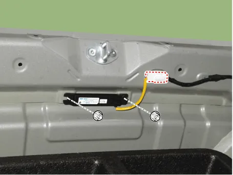
| 3. | Remove the trunk antenna (B) after disconnect the connector (A) and loosening the mounting nuts.
|
| 1. | Disconnect the negative (-) battery terminal. |
| 2. | Remove the rear bumper cover. (Refer to Body - "Rear Bumper Cover") |
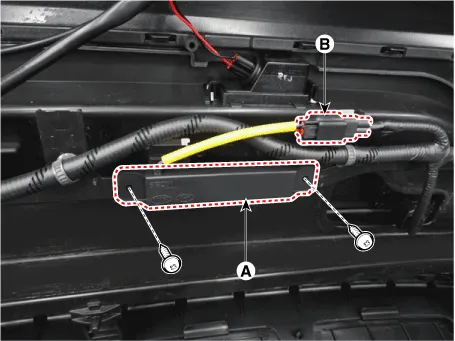
| 3. | Remove the rear bumper antenna (A) after disconnect the connector (B) and loosening the mounting nuts.
|
| 1. | Disconnect the negative (-) battery terminal. |
| 2. | Remove the front left wheel guide. (Refer to Body - "Front Wheel Guard") |
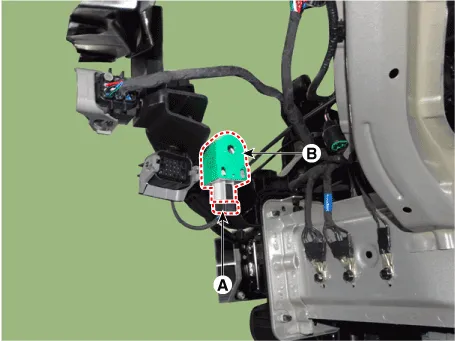
| 3. | Remove the buzzer (B) after disconnect the connector (A)
|
| 1. | Disconnect the negative (-) battery terminal. |
| 2. | Remove the front outside door handle. (Refer to Body - "Front Door Outside Handle")
|
| Inspection |
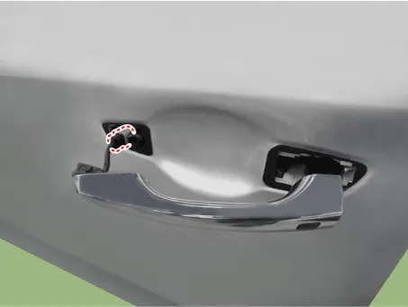
| 1. | Disconnect the front door outside handle connector (A).
|
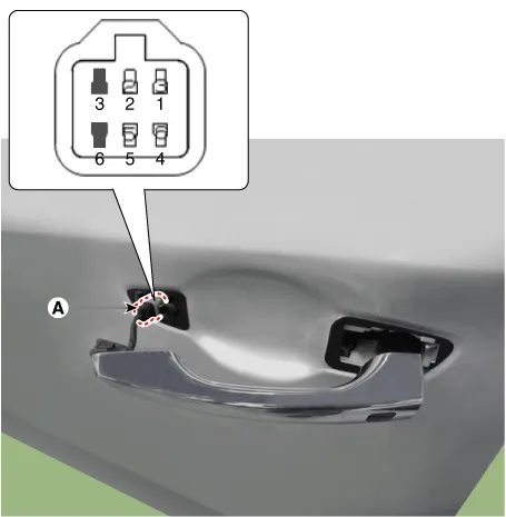
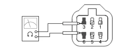
| 2. | Check for continuity between terminals No 3 and No 6.
|

| Installation |
| 1. | Install the smart key unit. |
| 2. | Install the smart key unit mounting bolts and connect the connector. |
| 3. | Install the glove box. |
| 4. | Install the negative (-) battery terminal and check the smart key system. |
| 1. | Install the interior 1 antenna. |
| 2. | Install the crash pad center panel. |
| 3. | Install the negative (-) battery terminal and check the smart key system. |
| 1. | Install the interior 2 antenna. |
| 2. | Install the console rear complete assembly. |
| 3. | Install the negative (-) battery terminal and check the smart key system. |
| 1. | Trunk mounted antenna. |
| 2. | Install the rear transverse trim. |
| 3. | Install the negative (-) battery terminal and check the smart key system. |
| 1. | Install the rear bumper antenna. |
| 2. | Install the rear bumper cover. |
| 3. | Install the negative (-) battery terminal and check the smart key system |
| 1. | Install the outside handle. |
| 2. | Install the front outside door handle. |
| 3. | Install the negative (-) battery terminal and check the smart key system. |
Circuit Diagram
InspectionSelf Diagnosis with Scan ToolIt will be able to diagnose defects of SMART KEY system with GDS quickly. GDS can operates actuator forcefully, input/output value monitoring and self diagnosis.
Other information:
Hyundai Ioniq (AE) 2017-2022 Service & Repair Manual: Photo Sensor. Description and operation
Description The photo sensor is located at the center of the defrost nozzles.The photo sensor contains a photovoltaic (sensitive to sunlight) diode. The solar radiation received by its light receiving portion, generates an electromotive force in proportion to the amount of radiation received which is transferred to the automatic temperature control
Hyundai Ioniq (AE) 2017-2022 Service & Repair Manual: Repair procedures
Diagnosis with GDS1.REAR CORENER RADAR system defects can be quickly diagnosed with the GDS. GDS operates actuator quickly to monitor, input/output value and self diagnosis.2.Connect the cable of GDS to the data link connector in driver side crash pad lower panel, turn the power on GDS.
Categories
- Manuals Home
- Hyundai Ioniq Owners Manual
- Hyundai Ioniq Service Manual
- Transmission Gear Oil. Repair procedures
- DCT(Dual Clutch Transmission) System
- General Information
- New on site
- Most important about car
