Hyundai Ioniq (AE): Smart Key System / Smart Key Diagnostic. Repair procedures
Hyundai Ioniq (AE) 2017-2022 Service & Repair Manual / Body Electrical System / Smart Key System / Smart Key Diagnostic. Repair procedures
| Inspection |
Self Diagnosis with Scan Tool
It will be able to diagnose defects of SMART KEY system with GDS quickly. GDS can operates actuator forcefully, input/output value monitoring and self diagnosis.
The following three features will be major problem in SMART KEY system.
| 1. | Problem in SMART KEY unit input. |
| 2. | Problem in SMART KEY unit. |
| 3. | Problem in SMART KEY unit output. |
So the following three diagnosis operates will be the major problem solution process.
| 4. | SMART KEY unit Input problem : switch diagnosis |
| 5. | SMART KEY unit problem : communication diagnosis |
| 6. | SMART KEY unit Output problem : antenna and switch output diagnosis |
Switch Diagnosis
| 1. | Connect the cable of GDS to the data link connector in driver side crash pad lower panel, turn the power on GDS. |
| 2. | Select the vehicle model and then SMART KEY system. |
| 3. | Select the "SMART KEY Unit". |
| 4. | After IG ON, select the "Current Data".
|
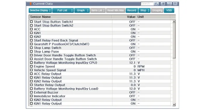
| 5. | You can see the situation of each switch on scanner after connecting the "current data" process.
|
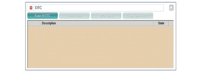
Communication Diagnosis with GDS (Self Diagnosis)
| 1. | Communication diagnosis checks that the each linked components operates normal. |
| 2. | Connect the cable of GDS to the data link connector in driver side crash pad lower panel. |
| 3. | After IG ON, select the "DTC".
|
Antenna Actuation Diagnosis
| 1. | Connect the cable of GDS to the data link connector in driver side crash pad lower panel. |
| 2. | After IG ON, select the "Actation Test".
|
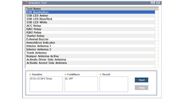
| 3. | Set the smart key near the related antenna and operate it with a GDS. |
| 4. | If the LED of smart key is blinking, the smart key is normal. |
| 5. | If the LED of smart key is not blinking, check the voltage of smart key battery. |
| 6. | Antenna actuation
|
Antenna Status Check
| 1. | Connect the cable of GDS to the data link connector in driver side crash pad lower panel. |
| 2. | Select the "Antenna Status Check".
|
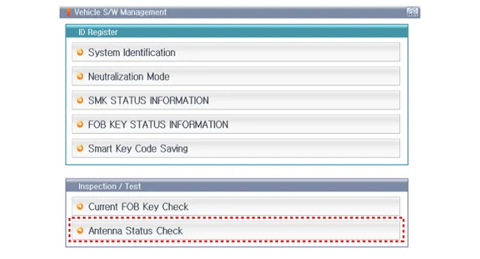
| 3. | After IG ON, select the "Antenna Status Check".
|
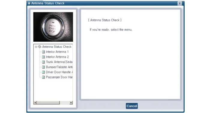
| 4. | Set the smart key near the related antenna and operate it with a GDS.
|

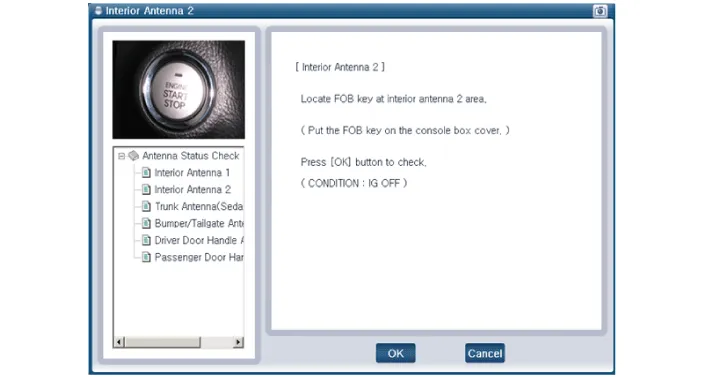
| 5. | If the smart key runs normal , the related antenna, smart key(transmission, reception) and exterior receiver are normal. |
| 6. | Antenna status
|
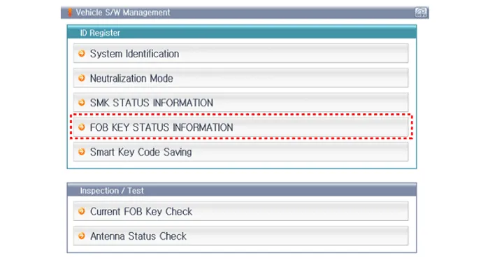
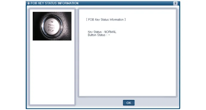
FOB Status Check
| 1. | Connect the cable of GDS to the data link connector in driver side crash pad lower panel. |
| 2. | After IG ON, select the "FOB Key Status Info".
|
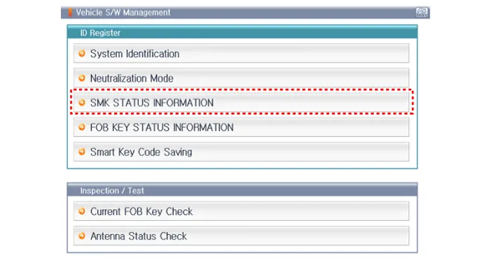
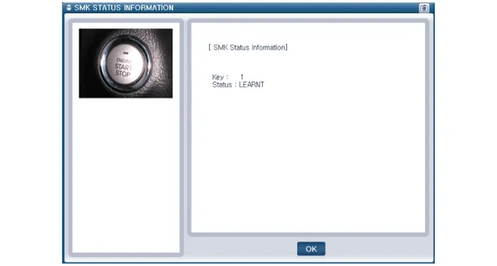
Smart Key Status Check
| 1. | Connect the cable of GDS to the data link connector in driver side crash pad lower panel. |
| 2. | After IG ON, select the "SMK Status Info".
|
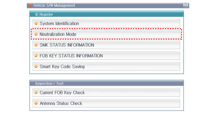
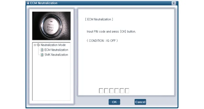
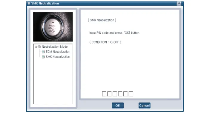
Neutralization Status Check
| 1. | Connect the cable of GDS to the data link connector in driver side crash pad lower panel. |
| 2. | After IG ON, select the "Neutralization Mode".
|

RemovalSmart Key Unit1.Disconnect the negative (-) battery terminal.2.Remove the glove box.(Refer to Body - "Glove Box Upper Cover Assembly")3.Remove the smart key unit (A) after disconnecting the connectors (B) and loosening the bolt and nut.
Other information:
Hyundai Ioniq (AE) 2017-2022 Service & Repair Manual: Schematic diagrams
Trouble Symptom ChartsComponent Parts and Function Outline Component part Function Cruise Control Switch Input the set speed and distance to the SCC ECU. Instrument Cluster Display various information inputted from SCC.
Hyundai Ioniq (AE) 2017-2022 Service & Repair Manual: Specifications
S
Categories
- Manuals Home
- Hyundai Ioniq Owners Manual
- Hyundai Ioniq Service Manual
- If the 12 Volt Battery is Discharged (Hybrid Vehicle)
- Suspension System
- Repair procedures
- New on site
- Most important about car

Copyright © 2026 www.hioniqae.com - 0.0158