
Hyundai Ioniq (AE): Tailgate Glass / Tailgate Glass Lower Glass. Repair procedures
Hyundai Ioniq (AE) 2017-2022 Service & Repair Manual / Body (Interior and Exterior) / Tailgate Glass / Tailgate Glass Lower Glass. Repair procedures
| Removal |
|

|

| 1. | Remove the tailgate trim. (Refer to Tailgate - "Tailgate Trim") |
| 2. | Remove the rear spoiler. (Refer to Body Side Molding - "Rear Spoiler") |
| 3. | Remove the inside rear combination lamp. (Refer to Body Electrical System - "Rear Combination Lamp") |
| 4. | Disconnect the hot wire connector (A).
|
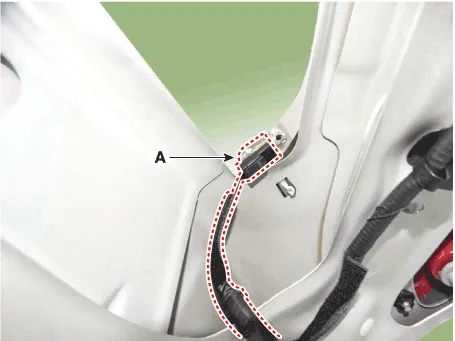
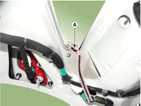
| 5. | Using a cutter (A) knife, carefully remove the tailgate lower glass.
|
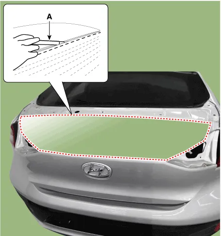
| 6. | Cut off the sealant on the edge (B) while pulling the piano wire (A) to the left and right.
|
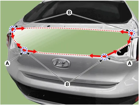
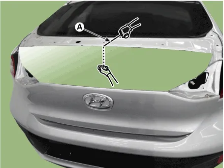
| 7. | Put in a piano wire (A) through the corner of the tailgate lower glass and insert wire grips into both ends of the wire.
|
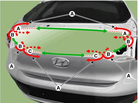
| 8. | Cut off the sealant on (A-A), (B-B), (C-C), while pulling a piano wire (A) to the left and right.
|
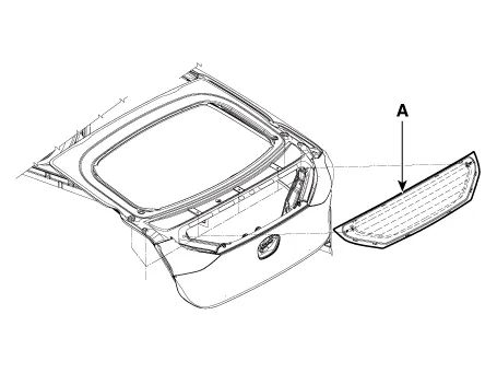
| 9. | Remove the tailgate lower glass (A).
|
| Installation |
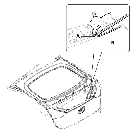
| 1. | Using a cutting knife (A), remove the remaining sealant (B) on the body panel.
|
| 2. | Apply the body primer to the bonding surface of body panel.
|
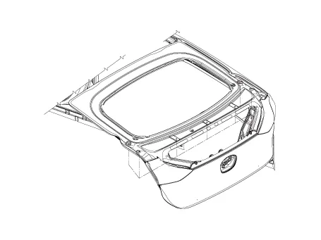
| 3. | Apply the glass primer to the outer edge of tailgate lower glass.
|
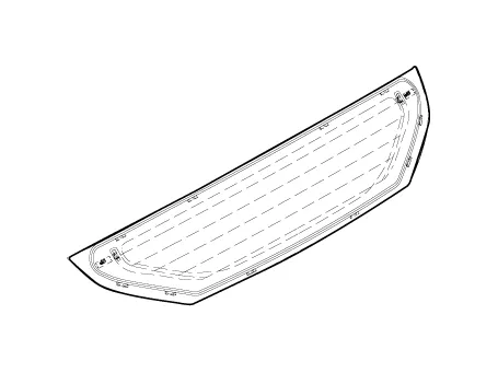
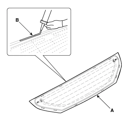
| 4. | Using a sealant gun, apply the sealant (B) to the edge of rear tailgate lower glass (A).
|
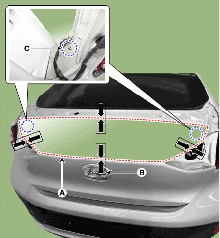
| 5. | Using the glass holder, adjust the tailgate lower glass (A) to fit the alignment marks (B) on the body and lightly push the tailgate lower glass to make the edges fully seated on the bonding surface of body.
|
| 6. | To make sure that the applied sealant is completely hardened, leave the car on a flat surface for at least 3 to 4 hours after installing the rear window glass.
|

| 7. | Conduct a leak testing.
|
| 8. | Install the inside rear combination lamp. (Refer to Body Electrical System - "Rear Combination Lamp") |
| 9. | Install the rear spoiler. (Refer to Body Side Molding - "Rear Spoiler") |
| 10. | Install the tailgate trim. (Refer to Tailgate - "Tailgate Trim") |
Removal • Put on gloves to prevent hand injuries. • Use seat covers to avoid damaging any surfaces.
Other information:
Hyundai Ioniq (AE) 2017-2022 Service & Repair Manual: Photo Sensor. Repair procedures
Inspection1.Turn the ignition switch ON.2.Connect the GDS.3.Emit intensive light toward the photo sensor using a lamp, and check the output voltage change.4.The voltage will rise with higher intensive light and reduce with lower intensive light.1. Auto light signal2.
Hyundai Ioniq (AE) 2017-2022 Service & Repair Manual: Components and components location
C
Categories
- Manuals Home
- Hyundai Ioniq Owners Manual
- Hyundai Ioniq Service Manual
- Troubleshooting
- If the 12 Volt Battery is Discharged (Hybrid Vehicle)
- Engine Clutch System
- New on site
- Most important about car

Copyright © 2026 www.hioniqae.com - 0.0189