
Hyundai Ioniq (AE): Tire Pressure Monitoring System / TPMS Receiver. Repair procedures
| Removal |
| 1. | Disconnect the negative (-) battery terminal. |
| 2. | Remove the glove box. (Refer to Body - "Glove Box Upper Cover Assembly") |
| 3. | Remove the smart key unit. (Refer to Body - "Smart Key Unit") |
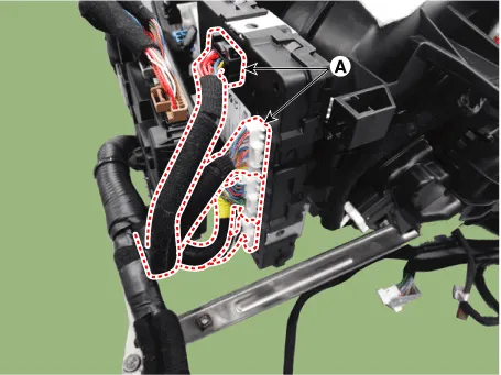
| 4. | Disconnect the body control module connectors (A).
|
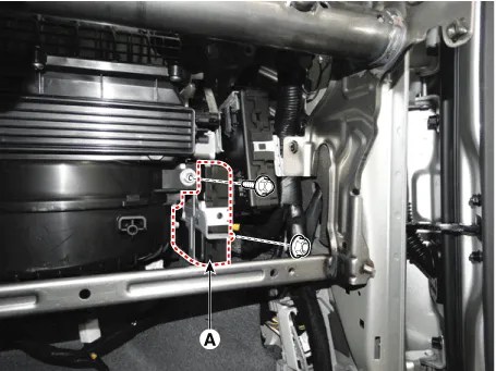
| 5. | Remove the body control module (A) after loosening the mounting nuts.
|
| Installation |
| 1. | Install the body control module. |
| 2. | Install the glove box upper cover assembly. |
| 3. | Connect the negative (-) battery terminal. |
| Adjustment |
| Diagnosis procedure by using diagnostic device |
| 1. | Connect self-diagnosis connector(16pins) located in the lower of driver side crash pad to self-diagnosis device, and then turn the self-diagnosis device after key is ON. |
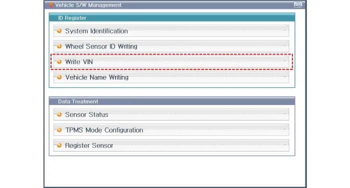
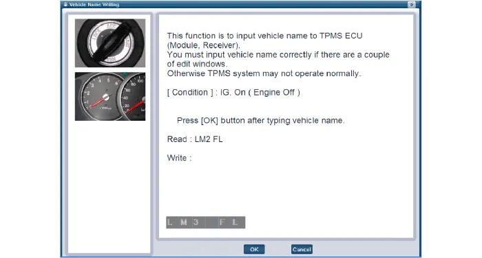
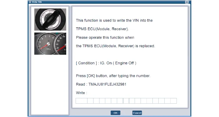
| 2. | Select the "vehicle model" and "TPMS" on GDS vehicle selection screen, then select OK. [Sensor ID Writing]
[Vehicle name input initialization]
[VIN input initialization]
|
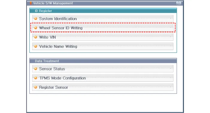
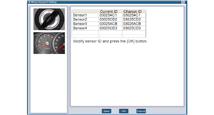
Description TPMS Receiver : BCM(body control module) integrated management1.Mode(1)Virgin State– The receiver as a sole part is shipped in this state.
Other information:
Hyundai Ioniq (AE) 2017-2022 Service & Repair Manual: emperature Control Actuator. Repair procedures
Inspection1.Turn the ignition switch OFF.2.Disconnect the temperature control actuator connector.3.Verify that the temperature control actuator operates to the cool position when connecting 12V to terminal 3 and grounding terminal 7.Verify that the temperature control actuator operates to the warm position when connected in reverse.
Hyundai Ioniq (AE) 2017-2022 Service & Repair Manual: Blower Motor. Repair procedures
Inspection1.Connect the battery voltage and check the blower motor rotation.2.If the blower motor does not operate well, substitute with a known-good blower motor and check for proper operation.3.Replace the blower motor if it is proved that there is a problem with it.
Categories
- Manuals Home
- Hyundai Ioniq Owners Manual
- Hyundai Ioniq Service Manual
- Jump Starting
- Components and components location
- Troubleshooting
- New on site
- Most important about car
