Hyundai Ioniq (AE): Head Lamp Leveling Device / Components and components location
Hyundai Ioniq (AE) 2017-2022 Service & Repair Manual / Body Electrical System / Head Lamp Leveling Device / Components and components location
| Component Location |
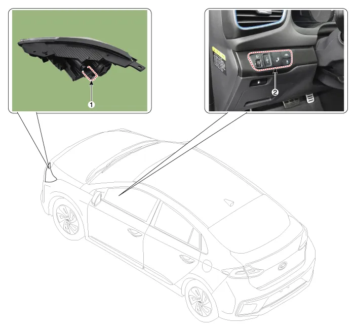
| 1. Head lamp leveling actuator | 2. Head lamp leveling switch |
SCHEMATIC DIAGRAM
Other information:
Hyundai Ioniq (AE) 2017-2022 Service & Repair Manual: Ambient Temperature Sensor. Components and components location
C
Hyundai Ioniq (AE) 2017-2022 Service & Repair Manual: Blower Unit. Components and components location
Component Location1. Blower unit assembly Components1. Duct Seal2. Intake duct case3. Air intake door assembly4. Intake door5. Seal6. Intake duct case (A)7. Air filter cover (A)8. Intake actuator9. Air filter cover10. Air filter 11. Blower unit pad12.
Categories
- Manuals Home
- Hyundai Ioniq Owners Manual
- Hyundai Ioniq Service Manual
- Front Disc Brake. Repair procedures
- Transmission Gear Oil. Repair procedures
- Checking the Coolant Level
- New on site
- Most important about car

Copyright © 2026 www.hioniqae.com - 0.0132