
Hyundai Ioniq (AE): Front Suspension System / Front Lower Arm. Repair procedures
| Removal |
| 1. | Loosen the wheel nuts slightly. Raise the vehicle, and make sure it is securely supported. |
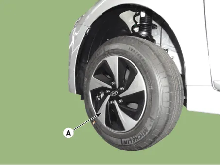
| 2. | Remove the front wheel and tire (A) from the front hub.
|

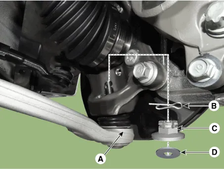
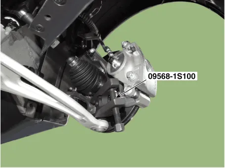
| 3. | Loosen the lower arm nut and then remove the lower arm ball joint by using SST(09568-1S100).
|
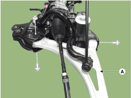
| 4. | Remove the front lower (A) arm after loosening the bolts & nuts.
|
| 5. | Install in the reverse order of removal. |
| 6. | Check the wheel Alignment. (Refer to Tires/Wheels - "Alignment") |
| Inspection |
| 1. | Check the bushing for wear and deterioration. |
| 2. | Check the lower arm for deformation. |
| 3. | Check the all bolts and nuts. |
Removal1.Loosen the wheel nuts slightly.Raise the vehicle, and make sure it is securely supported.2.Remove the front wheel and tire (A) from the front hub.
Removal1.Loosen the bolt (A) and then disconnect the universal joint assembly from the pinion of the steering gear box. Tightening torque : 32.
Other information:
Hyundai Ioniq (AE) 2017-2022 Service & Repair Manual: Mode Control Actuator. Description and operation
DescriptionThe mode control actuator is located at the heater unit.It adjusts the position of the mode door by operating the mode control actuator based on the signal of the A/C control unit. Pressing the mode select switch makes the mode control actuator shift in order of Vent → Bi-Level → Floor → Mix.
Hyundai Ioniq (AE) 2017-2022 Service & Repair Manual: Special service tools
Special Service Tools Tool Name / Number Illustration Description LKA Compensator(09964-C1100)Used for compensating front view camera unitBCW Sensor Correction Tool Set(09958-3T500)Used to correct the blind-spot radar unit.
Categories
- Manuals Home
- Hyundai Ioniq Owners Manual
- Hyundai Ioniq Service Manual
- If the 12 Volt Battery is Discharged (Hybrid Vehicle)
- Suspension System
- Engine Control/Fuel System
- New on site
- Most important about car
