Hyundai Ioniq (AE): Front Suspension System / Front Stabilizer Bar. Repair procedures
Hyundai Ioniq (AE) 2017-2022 Service & Repair Manual / Suspension System / Front Suspension System / Front Stabilizer Bar. Repair procedures
| Removal |
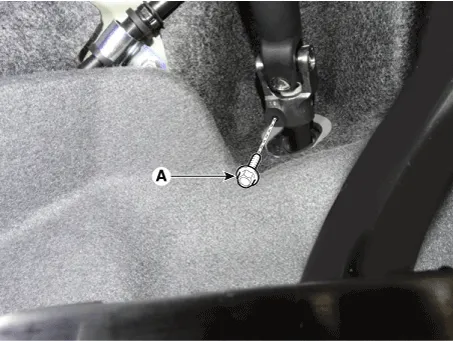
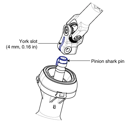
| 1. | Loosen the bolt (A) and then disconnect the universal joint assembly from the pinion of the steering gear box.
|

| 2. | Loosen the wheel nuts slightly. Raise the vehicle, and make sure it is securely supported. |
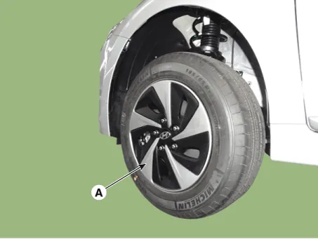
| 3. | Remove the front wheel and tire (A) from the front hub.
|
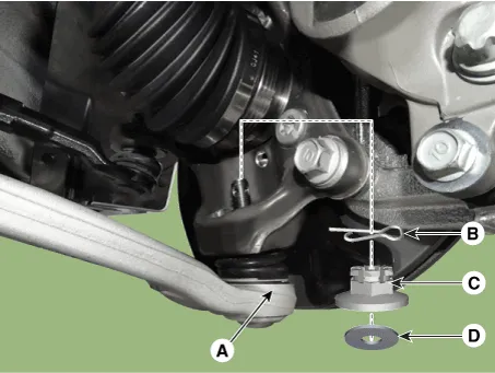
| 4. | Remove the tie rod end ball joint.
|
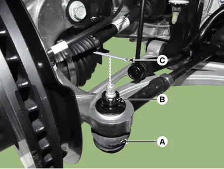
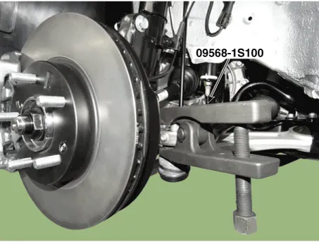
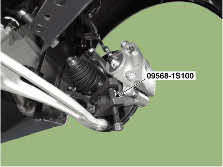
| 5. | Loosen the lower arm nut and then remove the lower arm ball joint by using SST(09568-1S100).
|
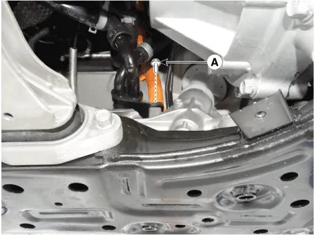
| 6. | Disconnect the stabilizer link with the front strut assembly after loosening the nut (A).
|

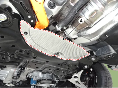
| 7. | Remove the heat protector (A).
|
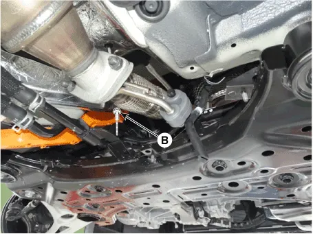
| 8. | Loosen the mounting bolt (A)&(B) then remove the pipe from the sub frame.
|
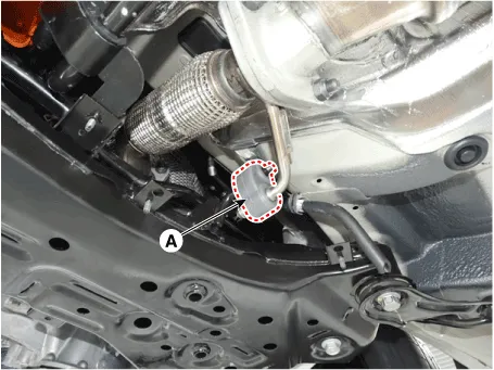
| 9. | Remove the muffler rubber hanger (A).
|
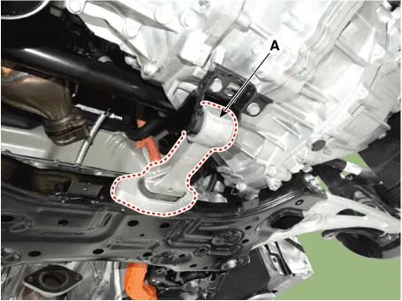
| 10. | Remove the roll rod stopper (A) by loosening the bolt and nut.
|
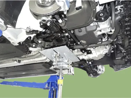
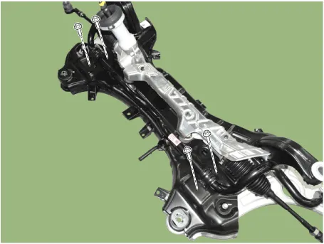
| 11. | Loosen the mounting bolts and then remove the stabilizer bar.
|
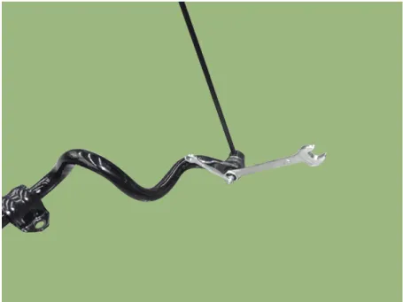
| 12. | Remove the stabilizer link.
|
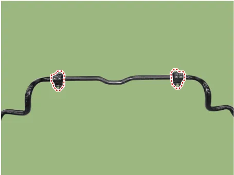
| 13. | Remove the bushing.
|
| 14. | Install in the reverse order of removal. |
| 15. | Check the wheel Alignment. (Refer to Tires/Wheels - "Alignment") |
| Inspection |
| 1. | Check the bushing for wear and deterioration. |
| 2. | Check the front stabilizer bar for deformation. |
| 3. | Check the front stabilizer link ball joint for damage. |
Removal1.Loosen the wheel nuts slightly.Raise the vehicle, and make sure it is securely supported.2.Remove the front wheel and tire (A) from the front hub.
Removal1.Loosen the bolt (A) and then disconnect the universal joint assembly from the pinion of the steering gear box. Tightening torque : M8 BOLT : 32.
Other information:
Hyundai Ioniq (AE) 2017-2022 Service & Repair Manual: Schematic diagrams
Trouble Symptom ChartsComponent Parts and Function Outline Component part Function Cruise Control Switch Input the set speed and distance to the SCC ECU. Instrument Cluster Display various information inputted from SCC.
Hyundai Ioniq (AE) 2017-2022 Service & Repair Manual: Front Radar Unit. Specifications
S
Categories
- Manuals Home
- Hyundai Ioniq Owners Manual
- Hyundai Ioniq Service Manual
- Repair procedures
- Suspension System
- Jump Starting
- New on site
- Most important about car

Copyright © 2026 www.hioniqae.com - 0.0125