Hyundai Ioniq (AE): Front Suspension System / Front Lower Arm. Repair procedures
Hyundai Ioniq (AE) 2017-2022 Service & Repair Manual / Suspension System / Front Suspension System / Front Lower Arm. Repair procedures
| Removal |
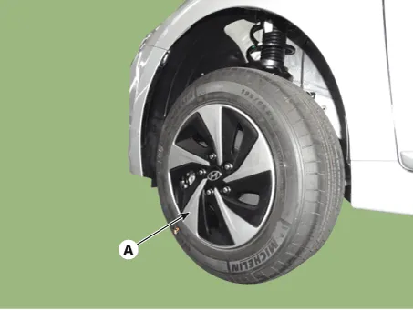
| 1. | Loosen the wheel nuts slightly. Raise the vehicle, and make sure it is securely supported. |
| 2. | Remove the front wheel and tire (A) from the front hub.
|

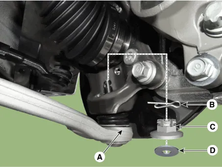
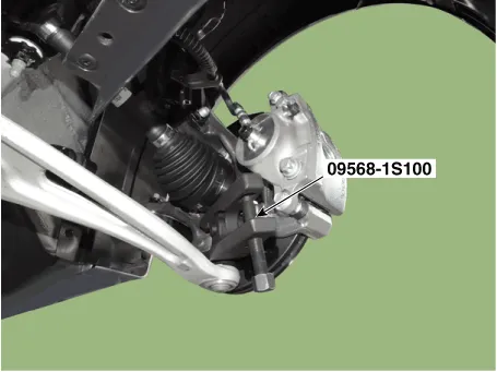
| 3. | Loosen the lower arm nut and then remove the lower arm ball joint by using SST(09568-1S100).
|
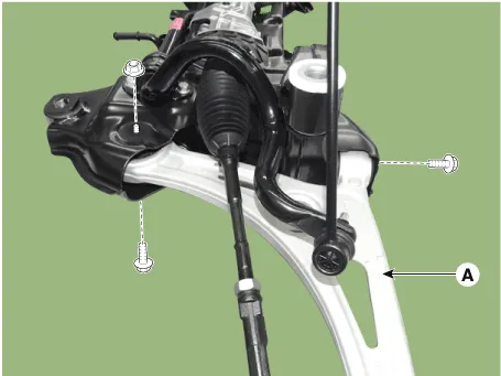
| 4. | Remove the front lower (A) arm after loosening the bolts & nuts.
|
| 5. | Install in the reverse order of removal. |
| 6. | Check the wheel Alignment. (Refer to Tires/Wheels - "Alignment") |
| Inspection |
| 1. | Check the bushing for wear and deterioration. |
| 2. | Check the lower arm for deformation. |
| 3. | Check the all bolts and nuts. |
Removal1.Loosen the wheel nuts slightly.Raise the vehicle, and make sure it is securely supported.2.Remove the front wheel and tire (A) from the front hub.
Removal1.Loosen the bolt (A) and then disconnect the universal joint assembly from the pinion of the steering gear box. Tightening torque : 32.
Other information:
Hyundai Ioniq (AE) 2017-2022 Service & Repair Manual: Heater Unit. Repair procedures
Replacement When prying with a flat-tip screwdriver or use a prying trim tool, wrap it with protective tape, and apply protective tape around the related parts, to prevent damage.1.Disconnect the negative (-) battery terminal.2.Recover the refrigerant with a recovery / recycling / charging station.
Hyundai Ioniq (AE) 2017-2022 Service & Repair Manual: Mode Control Actuator. Components and components location
C
Categories
- Manuals Home
- Hyundai Ioniq Owners Manual
- Hyundai Ioniq Service Manual
- Body (Interior and Exterior)
- Engine Mechanical System
- Hybrid Control System
- New on site
- Most important about car

Copyright © 2026 www.hioniqae.com - 0.0149