Hyundai Ioniq (AE): Air Conditioning System / Duct Sensor. Repair procedures
Hyundai Ioniq (AE) 2017-2022 Service & Repair Manual / Heating, Ventilation and Air Conditioning / Air Conditioning System / Duct Sensor. Repair procedures
| Inspection |
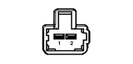
| 1. | Check that the voltage values of No. 1, 2 duct sensors change
Specification
|
| Replacement |
| [Duct sensor - Floor] |
| 1. | Disconnect the negative (-) battery terminal. |
| 2. | Remove the crash pad lower panel. (Refer to Body - "Crash Pad Lower Panel") |
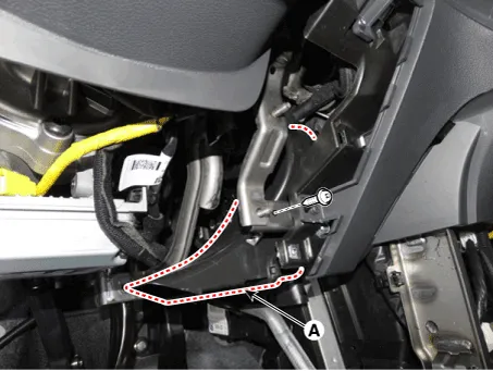
| 3. | Remove the driver's side shower duct (A) after loosening the screw.
|
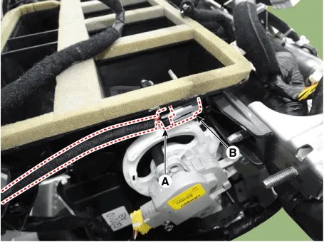
| 4. | Disconnect the duct sensor connector (A). |
| 5. | Hold the end of duct sensor (A) and then rotate it 90° clockwise. Remove the duct sensor (B) by pulling it.
|

| 6. | To install, reverse the removal procedure. |
| [Duct sensor - Vent] |
| 7. | Disconnect the negative (-) battery terminal. |
| 8. | Remove the main crash pad assembly. (Refer to Body - "Main Crash Pad Assembly") |
| 9. | Disconnect the duct sensor connector (A). |
| 10. | Hold the end of duct sensor (A) and then rotate it 90° clockwise. Remove the duct sensor (B) by pulling it.
|
| 11. | To install, reverse the removal procedure. |
Components Location1. Duct sensor (Vent)2. Duct sensor (Floor)
Other information:
Hyundai Ioniq (AE) 2017-2022 Service & Repair Manual: Evaporator Temperature Sensor. Repair procedures
Inspection1.Turn the ignition switch OFF.2.Disconnect the evaporator temperature sensor connector.3.Measure the resistance between terminal "+" and "-" of the evaporator temperature sensor.Specification Evaporator core temperature [°C (°F)] Resistance [KΩ]
Hyundai Ioniq (AE) 2017-2022 Service & Repair Manual: Description and operation
DescriptionThe smart cruise control system allows a driver to program the vehicle to control the speed and following distance by detecting the vehicle ahead without depressing the brake pedal and the accelerator pedal.1.Cruise speed control : The vehicle maintains the selected speed if there are not vehicles ahead.
Categories
- Manuals Home
- Hyundai Ioniq Owners Manual
- Hyundai Ioniq Service Manual
- Engine Control/Fuel System
- Suspension System
- Brake System
- New on site
- Most important about car

Copyright © 2026 www.hioniqae.com - 0.0124