Hyundai Ioniq (AE): Hybrid Control System / High voltage battery handling guide
Hyundai Ioniq (AE) 2017-2022 Service & Repair Manual / Hybrid Control System / High voltage battery handling guide
| High voltage battery system inspection guide |
|
| Classification | Inspection process | Inspection results | Measures | |||||||||||||
| Fire outside of the high voltage battery mount ※Example) Engine fire |
| High voltage battery insulation damaged | Remove the high voltage battery and repair the insulation process/coating. | |||||||||||||
| High voltage battery not damaged | DTC code | If a DTC code occurs, comply with DTC diagnosis guide and repair process. | ||||||||||||||
| No DTC code and battery appears normal | Do not replace the high voltage battery (if the battery is damaged and must be disposed of, perform the high voltage battery disposal process). | |||||||||||||||
| Fire in the high voltage battery mount ※Example) Trunk fire |
| High voltage battery appears damaged (heat, soot, etc.) | Remove the service disconnect plug and perform the salt water battery disposal process. | |||||||||||||
| High voltage battery insulation damaged | Remove the high voltage battery and repair the coating/insulation. | |||||||||||||||
| High voltage battery not damaged | DTC code | If a DTC code occurs, perform the repair process outlined in the DTC diagnosis guide. | ||||||||||||||
| No DTC code and battery appears normal | Do not replace the high voltage battery (if the battery is damaged and must be disposed of, perform the high voltage battery disposal process). | |||||||||||||||
3) Collision
| Classification | Inspection process | Inspection results | Measures | |||||||||||||
| Collision damage to areas other than the high voltage battery mount ※Example) Front/side collision |
| High voltage battery insulation damaged | Remove the high voltage battery and repair the coating/insulation. | |||||||||||||
| High voltage battery not damaged | DTC code | If a DTC code occurs, perform the repair process outlined in the DTC diagnosis guide. | ||||||||||||||
| No DTC code and battery appears normal | Do not replace the high voltage battery (if the battery is damaged and must be disposed of, perform the high voltage battery disposal process). | |||||||||||||||
| Collisions involving the high voltage battery mount ※Example) Rear-end collision |
| High voltage battery insulation damaged | ⇑ Follow the measures outlined above. ※ If the high voltage battery mount is inaccessible due to trunk or door damage, bend or cut the exterior panels without damaging the high voltage system and carry out the inspection and repair process. | |||||||||||||
| High voltage battery not damaged | DTC code | |||||||||||||||
| No DTC code and battery appears normal | ||||||||||||||||
4) Submersion
| Classification | Inspection process | Inspection results | Measures | |||||||||||||
| High voltage battery not submerged |
| High voltage battery insulation damaged | Remove the high voltage battery and repair the coating/insulation. | |||||||||||||
| High voltage battery not damaged | DTC code | If a DTC code occurs, perform the repair process outlined in the DTC diagnosis guide. | ||||||||||||||
| No DTC code and battery appears normal | Do not replace the high voltage battery (if the battery is damaged and must be disposed of, perform the high voltage battery disposal process). | |||||||||||||||
| High voltage battery submerged [Regardless of water conditions] |
| Carry out these measures regardless of the inspection results | Remove the high voltage battery and repair the coating/insulation. | |||||||||||||
Main Fuse Inspection
| 1. | Remove the main fuse. (Refer to Hybrid Control System - "Main Fuse") |
| 2. | Measure the resistance of main fuse.
|
| 3. | If the measured resistance is not within the specification, replace the main fuse. |
Checking for Welding in the High Voltage Main Relay
In order to safely remove the battery pack assembly, you must first inspect the high voltage main relay for signs of weld damage.
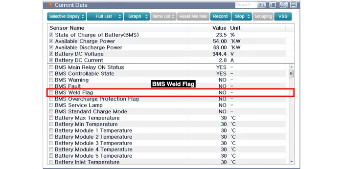
You can use Gloval Diagnostic System (GDS) service data to detect weld damage in the high voltage main relay.
| [Using GDS service data to check for main relay weld damage] |
| 1. | Connect the GDS to the self-diagnosis connector (DLC). |
| 2. | Turn on the ignition. |
| 3. | Check the BMS weld damage state in the GDS service data.
|
| [Using a Multimeter to measure weld damage] |
|
| 1. | Shut off the high voltage. (Refer to "High voltage Shut-off Procedures"). |
| 2. | Remove the rear seat cushion. (Refer to Body - "Rear Seat Assembly") |
| 3. | Remove the rear door scuff trim. (Refer to Body - "Door Scuff Trim") |
| 4. | Remove the inlet duct. (Refer to Hybrid Control System - "Cooling Duct") |
| 5. | Remove the high voltage battery rear cover. (Refer to High Voltage Battery System - "Case") |
| 6. | Disconnect the high voltage (-) connector (A) and high voltage (+) connector (B).
|
| 7. | Measure the high voltage main relay resistance and check for signs of weld damage.
|
Isolation Resistance Inpection
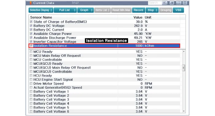
The high voltage isolation used in hybrid systems can be checked using GDS service data or by measuring it directly.
| [Using GDS service data to check isolation resistance] |
| 1. | Connect the GDS to the self-diagnosis connector (DLC). |
| 2. | Turn on the ignition. |
| 3. | Check the isolation resistance in the GDS service data.
|
| [Measuring isolation resistance using an insulation tester (MΩ tester)] |
|
| 1. | Shut off the high voltage circuit. (Refer to Hybrid Control System - "High Voltage Shut-off Procedures") |
| 2. | Remove the rear seat cushion. (Refer to Body - "Rear Seat Assembly") |
| 3. | Remove the rear door scuff trim. (Refer to Body - "Door Scuff Trim") |
| 4. | Remove the inlet cooling duct. (Refer to High Voltage Battery Cooling System - "Cooling Duct") |
| 5. | Remove the inlet cooling duct. (Refer to High Voltage Battery Cooling System - "Cooling Duct") |
| 6. | Remove the high voltage battery rear cover. (Refer to High Voltage Battery System - "Case") |
| 7. | Connect the insulation tester (-) terminal (A) to the battery system case (or ground).
|
| 8. | Connect the insulation tester (+) terminal to the high voltage battery (+) and (-). Measure the resistance. [Measure the isolation resistance on the power relay assembly high voltage power terminal (+)]
[Measure the isolation resistance on the power relay assembly high voltage power terminal (-)]
[Measure the isolation resistance on the power relay assembly inverter power terminal (+)]
[Measure the isolation resistance on the power relay assembly inverter power terminal (-)]
|
| Handling Guide for Storing, Transporting, and Disposing of High Voltage Battery Systems |
1. High voltage battery system handling process
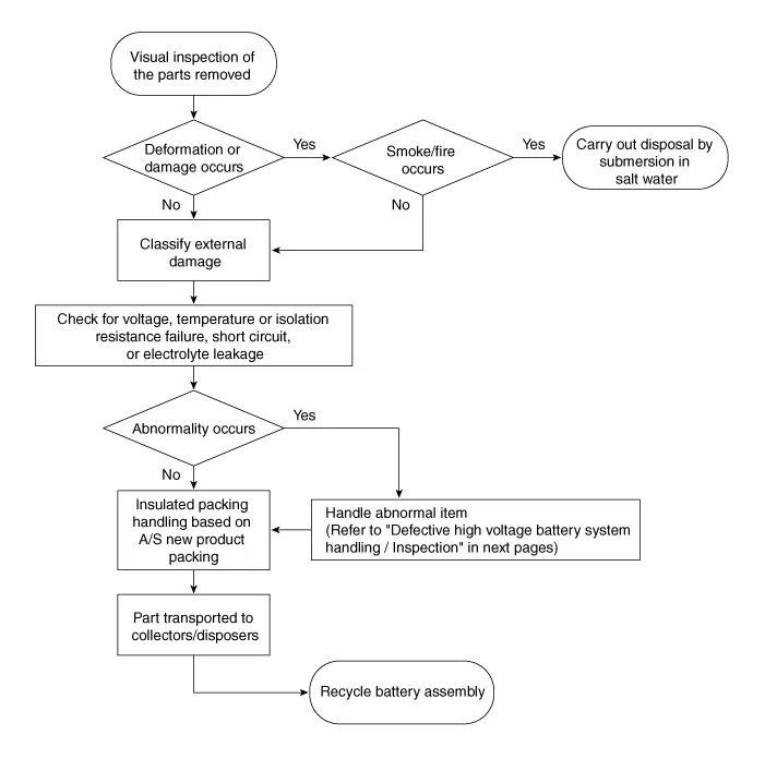
2. Defective high voltage battery system handling / Inspection
| Classification | Item | Measures | |||||||||||||||||||||||||||||||||||||||
| Undamaged Battery | Storage | Remove the service disconnect and store the battery under the same conditions as a new battery. | |||||||||||||||||||||||||||||||||||||||
| Transport | Minimize impacts and ensure the battery does not come in contact with other parts. | ||||||||||||||||||||||||||||||||||||||||
| Disposal | Transport the battery to the designated disposer | ||||||||||||||||||||||||||||||||||||||||
| Damaged battery | Common | Inspection method |
| ||||||||||||||||||||||||||||||||||||||
| Damaged battery | Damaged battery check results : normal | Storage | Remove the service disconnect plug and store the battery under the same conditions as a new battery. | ||||||||||||||||||||||||||||||||||||||
| Transport | Minimize impacts and ensure the battery does not come in contact with other parts. | ||||||||||||||||||||||||||||||||||||||||
| Disposal | Transport the battery to the designated disposer; discharge it by submersing it completely in salt water and carry out the disposal procedure. | ||||||||||||||||||||||||||||||||||||||||
| Damaged battery check results : abnormal | Storage | Remove the service disconnect plug; insulate all exposed terminals; place the battery in a cool, dry place away from volatile or combustible substances; use insulating materials (insulation tape, rubber caps, etc.) or vinyl to wrap the battery; use anti-shock materials inside the box. â–¶ Insulation action : Refer to "Take insulation actions for parts that may short circuit. â–¶ Packing : Abnormal battery must be packed as same as a new battery. | |||||||||||||||||||||||||||||||||||||||
| Transport | Minimize impacts and ensure the battery does not come in contact with other parts. | ||||||||||||||||||||||||||||||||||||||||
| Disposal | Transport the battery to the designated disposer; discharge it by submersing it completely in salt water and carry out the disposal procedure. | ||||||||||||||||||||||||||||||||||||||||
Voltage Check
|
| 1. | Measure the voltage between the service disconnect plug upper (+) terminal and [High voltage battery -PRA] connecting cable (-) terminal. → Specification : About 150V |
| 2. | Measure the voltage between the service disconnect plug lower (-) terminal and [High voltage battery -PRA] connecting cable (+) terminal. → Specification : About 120V
|
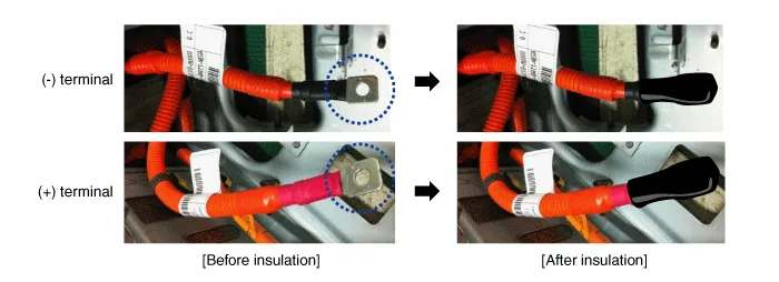
Take insulation actions for parts that may short circuit
| 1. | High voltage battery - PRA cable terminal
|
| 2. | BMS voltage sensing connector
â–¶ Insulation actions
|
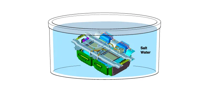
High Voltage Battery System Discharge Procedure on Disposal
|
High voltage batteries can cause electric shocks or other injuries. If the following symptoms are detected in a high voltage battery, discharge it as soon as possible by submersing it in salt water.
|
|
High Voltage Shut-off Procedures • Be sure to read and follow the "General Safety Information and Caution" before doing any work related with the high voltage system.
Procedure for entering engine forced activation modeIf the engine needs to be running constantly while the vehicle is stopped to inspect emission gas or perform maintenance on the vehicle, follow below procedure to enter engine forced activation mode.
Other information:
Hyundai Ioniq (AE) 2017-2022 Service & Repair Manual: Blower Unit. Components and components location
Component Location1. Blower unit assembly Components1. Duct Seal2. Intake duct case3. Air intake door assembly4. Intake door5. Seal6. Intake duct case (A)7. Air filter cover (A)8. Intake actuator9. Air filter cover10. Air filter 11. Blower unit pad12.
Hyundai Ioniq (AE) 2017-2022 Service & Repair Manual: Components and components location
C
Categories
- Manuals Home
- Hyundai Ioniq Owners Manual
- Hyundai Ioniq Service Manual
- Maintenance
- Engine Mounting. Components and components location
- Engine Mechanical System
- New on site
- Most important about car
Copyright © 2025 www.hioniqae.com - 0.0157


