
Hyundai Ioniq (AE): Keyless Entry And Burglar Alarm / Repair procedures
| Inspection |
|

Front Door Lock Module Inspection
| 1. | Remove the front door trim. (Refer to Body - "Front Door Trim") |
| 2. | Remove the front door module. (Refer to Body - "Front Door Module") |
| 3. | Disconnect the connector from the actuator.
| |||||||||||||||||||||||||||||
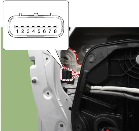
| 4. | Check actuator operation by connecting power and ground according to the table. To prevent damage to the actuator, apply battery voltage only momentarily.
|
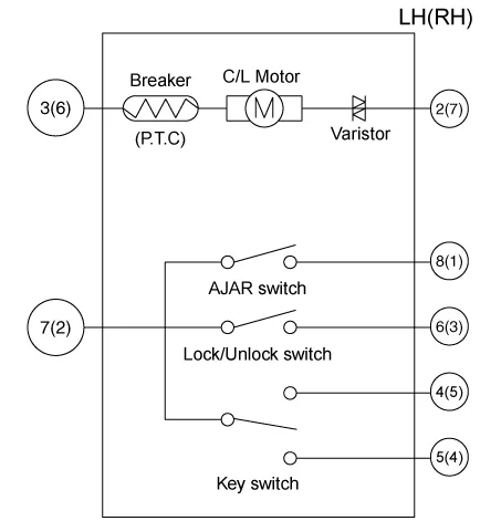
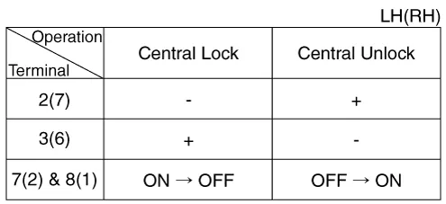
Rear Door Lock Module Inspection
| 1. | Remove the rear door trim. (Refer to Body - "Rear Door Trim") |
| 2. | Remove the rear door module. (Refer to Body - "Rear Door Module") |
| 3. | Disconnect the connectors from the actuator.
| |||||||||||||||||||||||||||||
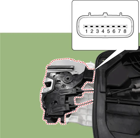
| 4. | Check actuator operation by connecting power and ground according to the table. To prevent damage to the actuator, apply battery voltage only momentarily.
|
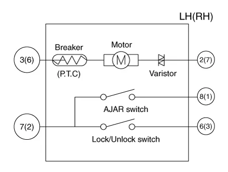
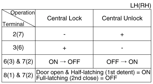
Tailgate Lock Module Inspection
| 1. | Remove the tailgate lid trim. (Refer to Body - "Tailgate Lid Trim") |
| 2. | Disconnect the connector from the actuator
|
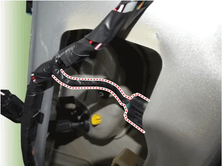
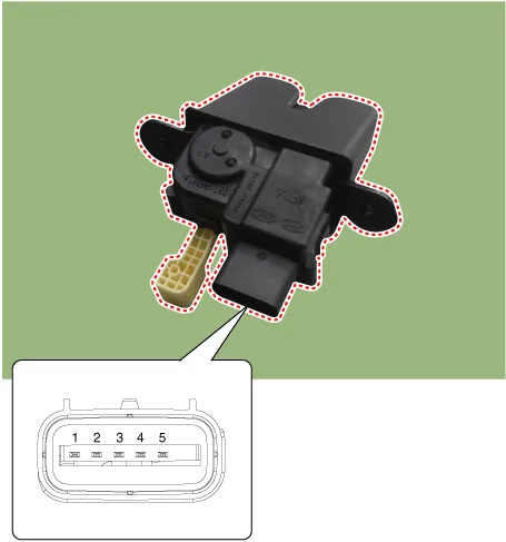
| 3. | Check actuator operation by connecting power and ground according to the table. To prevent damage to the actuator, apply battery voltage only momentarily.
|
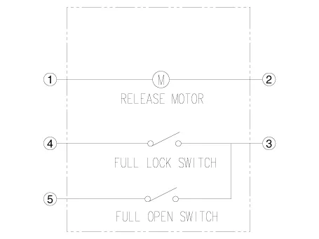
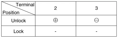
| 4. | Checking the trunk of the vehicle power option power refers to the tailgate lock module. |
Hood Switch
| 1. | Disconnect the connector (A).
|
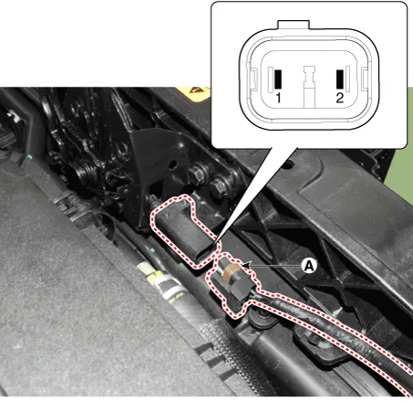
| 2. | Check for continuity between the terminals and ground according to the table (Refer to Body - "Hood Latch")
|

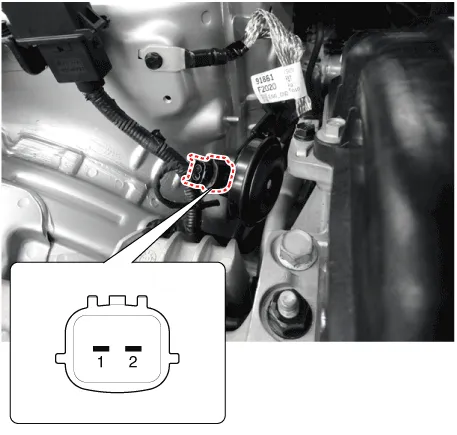
Burglar Horn Inspection
| 1. | Remove the burglar horn (A) after loosening the mounting bolts and disconnecting the connector (B).
|
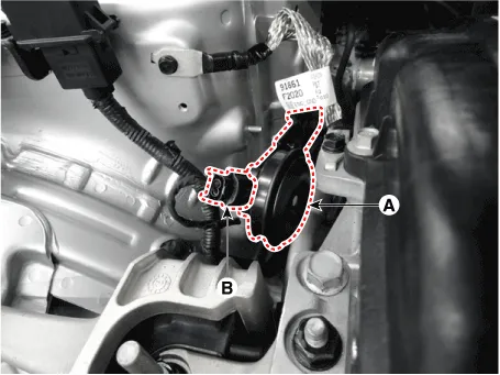
| 2. | Test the burglar horn by connecting battery power to the terminal 2 and ground the terminal 1.
|
DescriptionBurglar Alarm State [B/A State] B/A State Description DISARM1) In "DISARM" state, no vehicle start inhibition.
Other information:
Hyundai Ioniq (AE) 2017-2022 Service & Repair Manual: Intake Actuator. Components and components location
C
Hyundai Ioniq (AE) 2017-2022 Service & Repair Manual: General safety information and caution
General Safety Information and CautionBe careful of the following precautions when driving the vehicle using the smart cruise control system. • The smart cruise control system may have limits in detecting distance to the vehicle ahead due to road and traffic conditions.
Categories
- Manuals Home
- Hyundai Ioniq Owners Manual
- Hyundai Ioniq Service Manual
- Jump Starting
- Engine Control/Fuel System
- Engine Mechanical System
- New on site
- Most important about car

Copyright © 2026 www.hioniqae.com - 0.0175