Hyundai Ioniq (AE): Seat Electrical / Air Ventilation Seat. Repair procedures
| Removal |
| 1. | Disconnect the negative (-) battery terminal. |
| 2. | Remove the front seat. (Refer to Body - "Front Seat Assembly") |
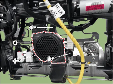
| 3. | Remove the blower duct.
|
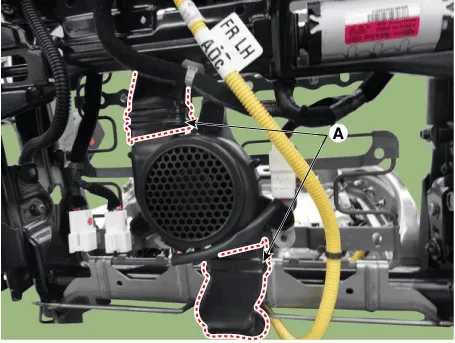
| 4. | Remove the blower FAN (A) after removing the screws.
|
| 1. | Disconnect the negative (-) battery terminal. |
| 2. | Remove the front seat. (Refer to Body - "Front seat Assembly") |
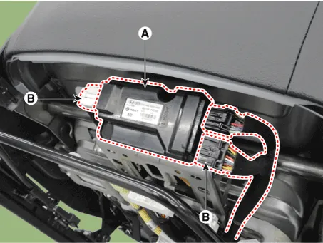
| 3. | Loosening the screws from the ventilation seat unit.
|
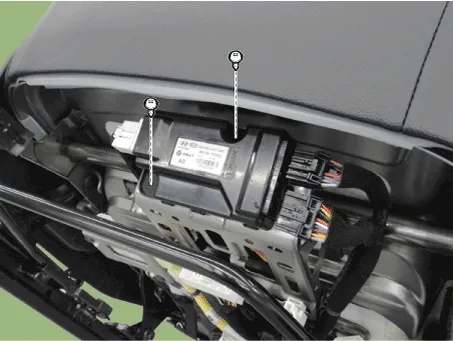
| 4. | Remove the ventilation seat unit (A) after disconnect the connectors (B).
|
| Installation |
| 1. | Install the blower fan. |
| 2. | Install the duct. |
| 3. | Install the front seat assembly. |
| 4. | Connect the negative (-) battery terminal. |
| 1. | Install the ventilation seat unit. |
| 2. | Install the front seat assembly. |
| 3. | Connect the negative (-) battery terminal. |
| Inspection |
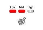
| 1. | You can enter the diagnosis mode by turning the heater seat button on. |
| 2. | You can enter the diagnosis mode by referring to following description. |
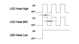
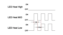
| 3. | Press the heating wire switch as shown below.
|
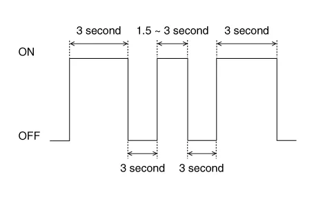
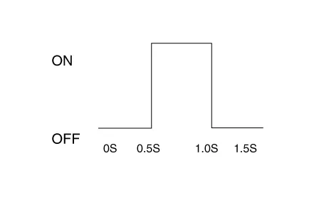
| 4. | When the vehicle enters the diagnostic mode, the three LEDs (Low, Mid, High) in the heating wire section blinks once for 0.5 seconds.
|
| 5. | After entering the diagnostic mode, check the LED status to identify the error.
|
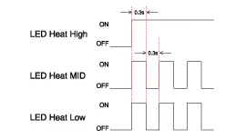
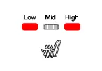
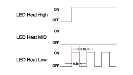
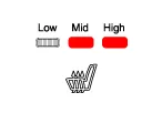
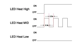
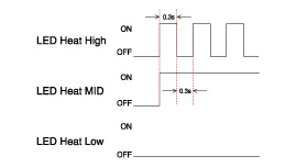
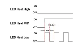
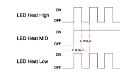
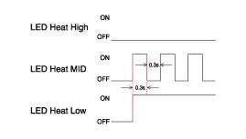
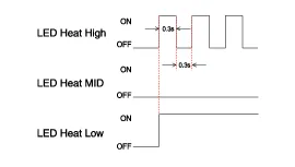
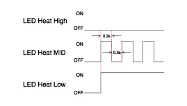
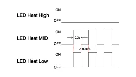
| 6. | You can check the malfunctioning by checking the blinking LED. |
| 7. | The failure data is recorded to the memory by the ventilation seat unit. |
| 8. | Press the heating wire seat switch on the passenger side for 5 seconds or more to make the LED blink four times and delete the failure data in the memory. |
| 9. | Pressing the IGN OFF button will end the diagnosis mode for the heater seat. |
| 10. | You can check whether the heating seat system works properly after turning the IGN ON. If you want to check the error code, you can refer to the procedure of 2 above. |
Circuit Diagram NO Connector A Connector B Connector C 1Ventilation seat unit (IGN1)Driver ventilation LED (Low)Ventilation heater power2Driver bolwer powerDriver ventilation LED (mid)Driver heater power3Driver bolwer SpeedDriver ventilation LED (High)-4Driver RPM inputDriver NTC (+)Heater ground5heater switch (Driver)-Ventilation heater power6Ventilation switch (Driver)--7-Driver NTC (-)Passenger heater power8Driver heater led (Low)Driver blower ground-9Driver heater led (mid)Driver ventilation LED (Low)-10Driver heater led (High)Driver ventilation LED (mid)Heater ground11Ventilation seat unit (IGN 2)Driver ventilation LED (High)12Passenger blower powerPassenger NTC (+)13Passenger blower speed-14Passenger blower RPM input-15Passenger heater switchPassenger NTC (-)16Passenger ventilation switchPassenger blower ground17-18Passenger ventilation LED (Low)19Passenger ventilation LED (mid)20Passenger ventilation LED (High)
Removal1.Disconnect the negative (-) battery terminal.2.Remove the front seat assembly.(Refer to Body - "Front Seat Assembly")3.Remove the seat back.(Refer to Body - "Front Seat Back Cover")4.
Other information:
Hyundai Ioniq (AE) 2017-2022 Service & Repair Manual: A/C Pressure Transducer. Repair procedures
Inspection • Before measuring the pressure of the refriferant line, check whether the refrigerant amount is charged in accordance with the specified charging amount.(Refer to Heating, Ventilation, Air Conditioning - "Specifications")1.
Hyundai Ioniq (AE) 2017-2022 Service & Repair Manual: Auto Defogging Sensor. Repair procedures
Diagnosis With GDS1.The heating, ventilation and air conditioning can be quickly diagnosed failed parts with vehicle diagnostic system (GDS).※ The diagnostic system (GDS) provides the following information.(1) Self diagnosis : Checking the failure code (DTC) and display.
Categories
- Manuals Home
- Hyundai Ioniq Owners Manual
- Hyundai Ioniq Service Manual
- Jump Starting
- Transmission Gear Oil. Repair procedures
- If the 12 Volt Battery is Discharged (Hybrid Vehicle)
- New on site
- Most important about car
