Hyundai Ioniq (AE): Seat Electrical / Air Ventilation Seat. Schematic diagrams
Hyundai Ioniq (AE) 2017-2022 Service & Repair Manual / Body Electrical System / Seat Electrical / Air Ventilation Seat. Schematic diagrams
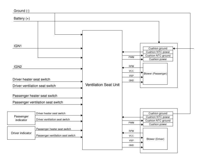
| Circuit Diagram |
|
NO
|
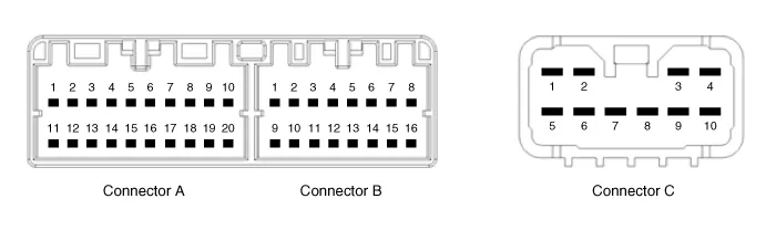
Connector A
|
Connector B
|
Connector C
|
| 1 | Ventilation seat unit (IGN1) | Driver ventilation LED (Low) | Ventilation heater power |
| 2 | Driver bolwer power | Driver ventilation LED (mid) | Driver heater power |
| 3 | Driver bolwer Speed | Driver ventilation LED (High) | - |
| 4 | Driver RPM input | Driver NTC (+) | Heater ground |
| 5 | heater switch (Driver) | - | Ventilation heater power |
| 6 | Ventilation switch (Driver) | - | - |
| 7 | - | Driver NTC (-) | Passenger heater power |
| 8 | Driver heater led (Low) | Driver blower ground | - |
| 9 | Driver heater led (mid) | Driver ventilation LED (Low) | - |
| 10 | Driver heater led (High) | Driver ventilation LED (mid) | Heater ground |
| 11 | Ventilation seat unit (IGN 2) | Driver ventilation LED (High) | |
| 12 | Passenger blower power | Passenger NTC (+) | |
| 13 | Passenger blower speed | - | |
| 14 | Passenger blower RPM input | - | |
| 15 | Passenger heater switch | Passenger NTC (-) | |
| 16 | Passenger ventilation switch | Passenger blower ground | |
| 17 | - | ||
| 18 | Passenger ventilation LED (Low) | ||
| 19 | Passenger ventilation LED (mid) | ||
| 20 | Passenger ventilation LED (High) |
Component Location[Front Ventilation Seat]1. Ventilation seat unit (Assist seat only)2. Ventilation seat blower
Removal[Ventilation Blower]1.Disconnect the negative (-) battery terminal.2.Remove the front seat.(Refer to Body - "Front Seat Assembly") 3.Remove the blower duct.
Categories
- Manuals Home
- Hyundai Ioniq Owners Manual
- Hyundai Ioniq Service Manual
- Jump starting procedure
- Engine Mechanical System
- Engine Clutch System
- New on site
- Most important about car

Copyright © 2026 www.hioniqae.com - 0.0164