Hyundai Ioniq (AE): Audio / Audio Remote Control. Repair procedures
Hyundai Ioniq (AE) 2017-2022 Service & Repair Manual / Body Electrical System / Audio / Audio Remote Control. Repair procedures
| Inspection |
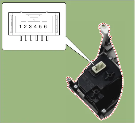
| 1. | Check for resistance between terminals in each switch position (LH).
[LH : Audio+B/TOOTH+VOICE]
|
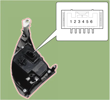
| 2. | Check for resistance between terminals in each switch position (RH).
[RH : Trip+Cruise+SCC]
|
| Removal |
| 1. | Disconnect the negative (-) battery terminal. |
| 2. | Remove the steering wheel assembly. (Refer to Steering System - "Steering Wheel") |
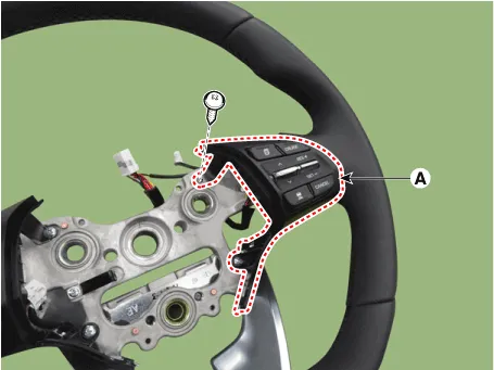
| 3. | Remove the steering back cover (A).
|
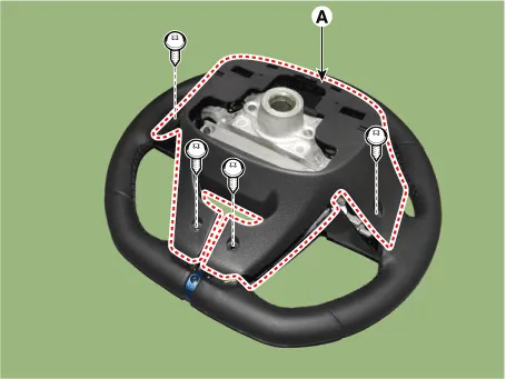
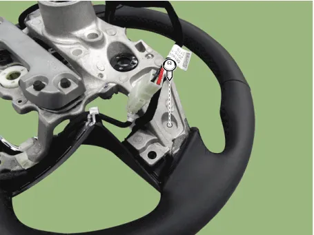
| 4. | Remove the steering remote control connector (A).
|
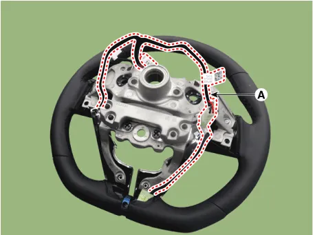
| 5. | Remove the steering remote control after loosening the screws.
|
| Installation |
| 1. | Install the steering wheel remote control after connecting the connector. |
| 2. | Connect the negative (-) battery terminal. |
Circuit Diagram[Audio+B/Tooth][Audio+B/Tooth+Voice][Trip][Trip+Cruise][Trip+Cruise+SCC]
Circuit Diagram
Other information:
Hyundai Ioniq (AE) 2017-2022 Service & Repair Manual: Auto Defoging Actuator. Repair procedures
Inspection1.Turn the ignition switch OFF. 2.Disconnect the auto defogging connector. 3.Verify that the auto defogging actuator operates to the open position when connecting 12V to terminal 3 and grounding terminal 4. Verify that the auto defogging actuator operates to the close position when connected in reverse.
Hyundai Ioniq (AE) 2017-2022 Service & Repair Manual: High voltage shut-off procedures
High Voltage Shut-off Procedures • Be sure to read and follow the "General Safety Information and Caution" before doing any work related with the high voltage system. Failure to follow the safety instructions may result in serious electrical injuries.
Categories
- Manuals Home
- Hyundai Ioniq Owners Manual
- Hyundai Ioniq Service Manual
- Engine Control/Fuel System
- Jump Starting
- If the 12 Volt Battery is Discharged (Hybrid Vehicle)
- New on site
- Most important about car

Copyright © 2026 www.hioniqae.com - 0.011