Hyundai Ioniq (AE): Audio / Audio Remote Control. Schematic diagrams
| Circuit Diagram |
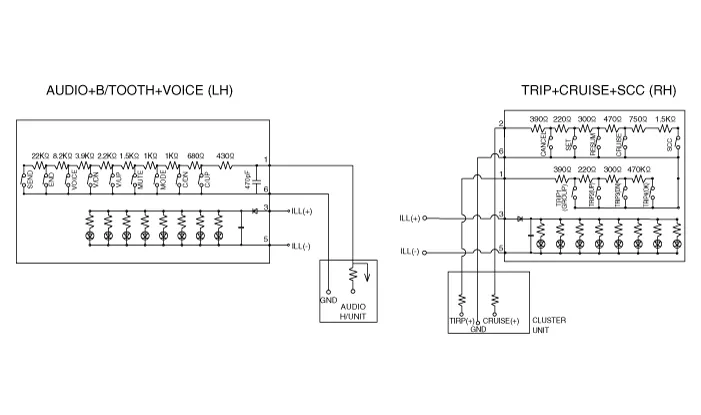
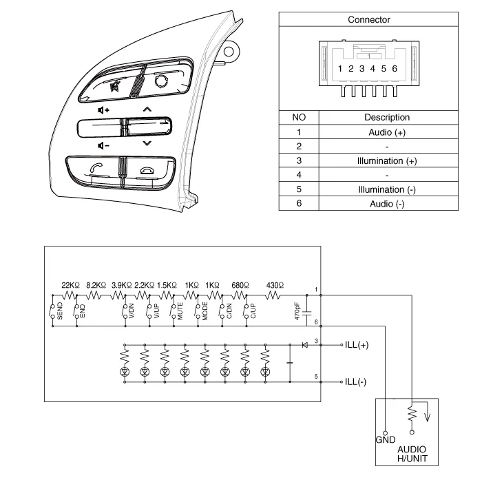
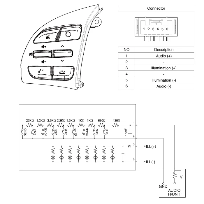
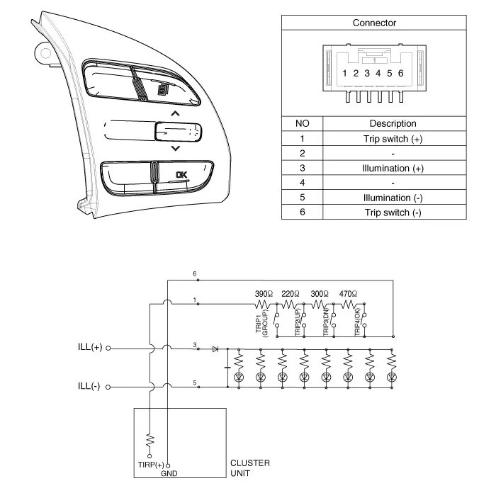
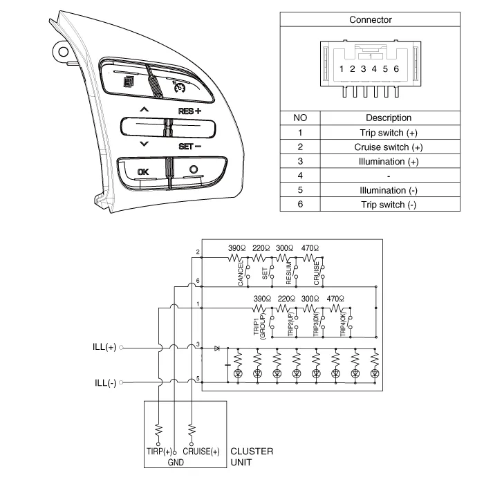
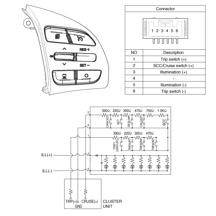
Components1. Left Remote Control Switch (Audio + Hands free)2. Right Remote Control Switch(Cruise+Trip Computer)
Inspection1.Check for resistance between terminals in each switch position (LH).[LH : Audio+B/TOOTH+VOICE] Switch Connector terminal Resistance (±5%) SEEK Up1-6430 ΩSEEK Down1.
Other information:
Hyundai Ioniq (AE) 2017-2022 Service & Repair Manual: Smart Cruise Control (SCC) Switch. Components and components location
C
Hyundai Ioniq (AE) 2017-2022 Service & Repair Manual: Warning Indicator. Repair procedures
RemovalWarning Indicator1.Disconnect the negative (-) battery terminal.2.Remove the mirror (A).InstallationWarning Indicator1.Install the outside mirror.2.Connect the negative (-) battery terminal.Inspection1.Apply battery voltage to each terminal as shown in the table and verify that the mirror operates properly.
Categories
- Manuals Home
- Hyundai Ioniq Owners Manual
- Hyundai Ioniq Service Manual
- Engine Mechanical System
- Checking the Coolant Level
- Engine Control/Fuel System
- New on site
- Most important about car
