Hyundai Ioniq (AE): Audio / Audio Remote Control. Components and components location
| Components |
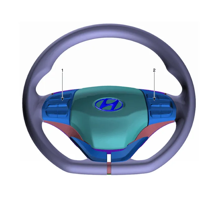
| 1. Left Remote Control Switch (Audio + Hands free) | 2. Right Remote Control Switch (Cruise+Trip Computer) |
InspectionAntenna Cable1.Check for continuity between the center poles of antenna cable.2.Check for continuity between the outer poles of antenna cable.
Circuit Diagram[Audio+B/Tooth][Audio+B/Tooth+Voice][Trip][Trip+Cruise][Trip+Cruise+SCC]
Other information:
Hyundai Ioniq (AE) 2017-2022 Service & Repair Manual: Auto Defogging Sensor. Description and operation
DescriptionThe auto defogging sensor is installed on the front window glass. The sensor judges and sends signal if moisture occurs to blow out wind for defogging. The air conditioner control module receives signal from the sensor and restrains moisture and eliminate defog by controlling the intake actuator, A/C, auto defogging actuator, blower moto
Hyundai Ioniq (AE) 2017-2022 Service & Repair Manual: Description and operation
System OverviewParking Distance Warning (PDW) is an electronic driving aid that warns the driver to be cautious while parking or driving at low speed. The sensor uses ultrasonic waves to detect objects within proximity of the vehicle.PDW consists of four RPS sensors which are detecting the obstacles and transmit the result separated into three war
Categories
- Manuals Home
- Hyundai Ioniq Owners Manual
- Hyundai Ioniq Service Manual
- Transmission Gear Oil. Repair procedures
- Jump starting procedure
- Jump Starting
- New on site
- Most important about car
