Hyundai Ioniq (AE): High Voltage Battery Control System / Battery Temperature Sensor. Repair procedures
Hyundai Ioniq (AE) 2017-2022 Service & Repair Manual / Hybrid Control System / High Voltage Battery Control System / Battery Temperature Sensor. Repair procedures
| Removal |
|

| 1. | Shut off the high voltage. (Refer to Hybrid Control System - "High Voltage Shut-off Procedures") |
| 2. | Remove the high voltage battery pack assembly. (Refer to High Voltage Battery System - "Battery Pack Assembly") |
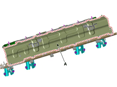
| 3. | Remove the battery pack assembly rear cover (A) after loosening the mounting nuts.
|
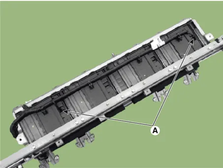
| 4. | Remove the battery temperature sensor (A).
|
| Installation |
|
| 1. | Install the battery temperature sensors in the reverse order of removal. |
| Inspection |
|
| 1. | Shut off the high voltage circuit. (Refer to Hybrid Control System - "High Voltage Shut-off Procedures") |
| 2. | Connect the GDS to the Data Link Connector (DLC). |
| 3. | Turn the ignition switch ON. |
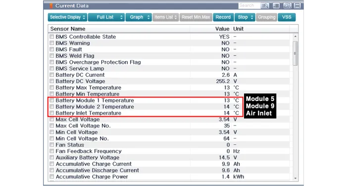
| 4. | Check the battery temperature in GDS service data.
|
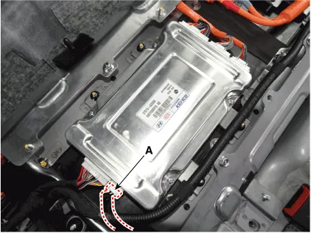
| 5. | Disconnect the battery temperature signal connector (A).
|
| 6. | Measure resistances of the temperature signal terminals (Refer to the table below), then compare the value with the GDS service data.
|
Circuit Diagram
Other information:
Hyundai Ioniq (AE) 2017-2022 Service & Repair Manual: A/C Pressure Transducer. Description and operation
DescriptionThe A/C Pressure Transducer (APT) converts the pressure value of high pressure line into voltage value after measuring it. By converted voltage value, engine ECU controls the cooling fan by operating it high speed or low speed. Engine ECU stops the operation of the compressor when the temperature of refrigerant line is very high or very
Hyundai Ioniq (AE) 2017-2022 Service & Repair Manual: Evaporator Core. Repair procedures
Replacement1.Disconnect the negative (-) battery terminal. 2.Remove the heater and blower assembly.(Refer to Heater - "Heater Unit") 3.Remove the evaporator core cover (A) after loosening the mounting screws.4.Pull out the evaporator temperature sensor (A) from the evaporator core.
Categories
- Manuals Home
- Hyundai Ioniq Owners Manual
- Hyundai Ioniq Service Manual
- Jump starting procedure
- Maintenance
- Checking the Coolant Level
- New on site
- Most important about car

Copyright © 2026 www.hioniqae.com - 0.014