Hyundai Ioniq (AE): Cylinder Head Assembly / CVVT & Camshaft. Description and operation
| Description |

| Operation Principle |
|

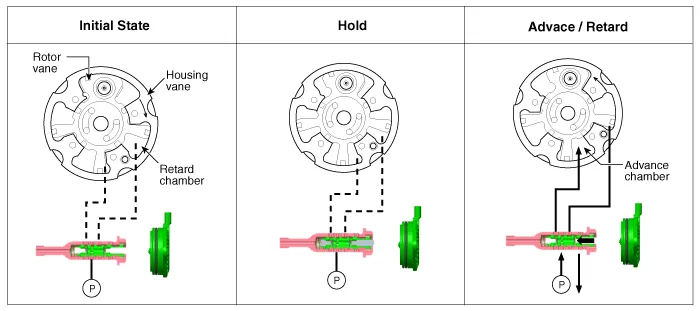
| 1. | Intake CVVT
|
| 2. | Exhaust CVVT
|
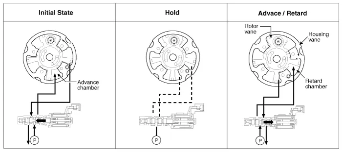
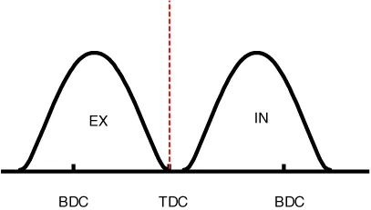
| [CVVT System Mode] |
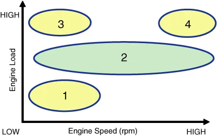
| (1) Low Speed / Low Load | (2) Part Load |
|
|
| (3) Low Speed / High Load | (4) High Speed / High Load |
|
|
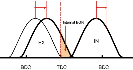
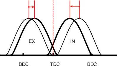
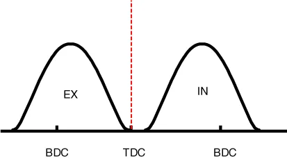
| Driving Condition | Exhaust Valve | Intake Valve | ||
| Valve Timing | Effect | Valve Timing | Effect | |
| (1) Low Speed /Low Load | Completely Advance | * Valve Under-lap * Improvement of combustion stability | Middle | * Valve Under-lap * Improvement of combustion stability |
| (2) Part Load | Retard | * Reduction of HC | Retard | * Delays the closing time of intake valve to reduce pumping loss |
| (3) Low Speed /High Load | Completely Advance | * Reduction of pumping loss | Advance | * Improvement of volumetric efficiency |
| (4) High Speed /High Load | Completely Advance | * Reduction of pumping loss | Advance | * Improvement of volumetric efficiency |
Components1. Camshaft bearing cap2. Front camshaft bearing cap3. Exhaust camshaft4. Intake camshaft5. Exhaust CVVT assembly6. Intake CVVT assembly
Removal ŌĆó Be sure to read and follow the ŌĆ£General Safety Information and CautionŌĆØ before doing any work related with the high voltage system.
Other information:
Hyundai Ioniq (AE) 2017-2022 Service & Repair Manual: Intake Actuator. Repair procedures
Inspection1.Turn the ignition switch OFF.2.Disconnect the intake actuator connector.3.Verify that the intake actuator operates to the fresh position when connecting 12V to terminal 3 and grounding terminal 4.Verify that the intake actuator operates to the recirculation position when connected in reverse.
Hyundai Ioniq (AE) 2017-2022 Service & Repair Manual: Repair procedures
Diagnosis with GDS1.REAR CORENER RADAR system defects can be quickly diagnosed with the GDS. GDS operates actuator quickly to monitor, input/output value and self diagnosis.2.Connect the cable of GDS to the data link connector in driver side crash pad lower panel, turn the power on GDS.
Categories
- Manuals Home
- Hyundai Ioniq Owners Manual
- Hyundai Ioniq Service Manual
- Engine Control/Fuel System
- Repair procedures
- Maintenance
- New on site
- Most important about car
