Hyundai Ioniq (AE): Cylinder Head Assembly / CVVT & Camshaft. Repair procedures
Hyundai Ioniq (AE) 2017-2022 Service & Repair Manual / Engine Mechanical System / Cylinder Head Assembly / CVVT & Camshaft. Repair procedures
| Removal |
|

|

|

| 1. | Shut off the High Voltage circuit. (Refer to General Information - "High Voltage Shutoff Procedure") |
| 2. | Disconnect the battery negative terminal. |
| 3. | Remove the cylinder head cover. (Refer to Cylinder Head Assembly - "Cylinder Head Cover") |
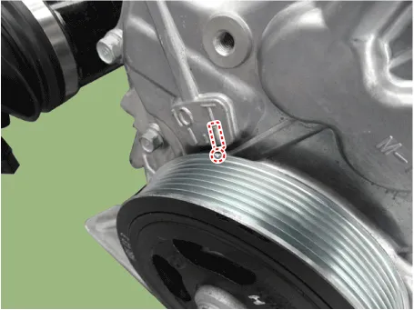
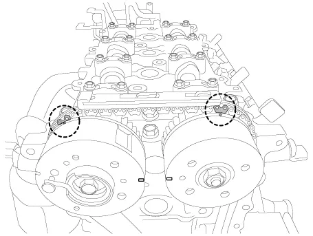
| 4. | Turn the crankshaft damper pulley and align its groove with the timing mark of the timing chain cover to set the piston of No.1 cylinder to the top dead center on compression stroke. |
| 5. | Set No.1 cylinder to TDC (Top dead center) on compression stroke.
|
| 6. | Remove the timing chain cover. (Refer to Timing System - "Timing Chain Cover") |
| 7. | Remove the timing chain. (Refer to Timing System - "Timing Chain") |
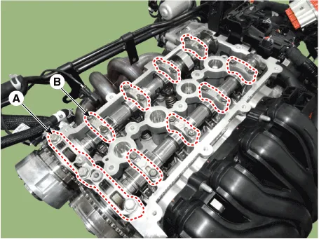
| 8. | Remove the front camshaft bearing cap (A) and the camshaft bearing caps (B).
|
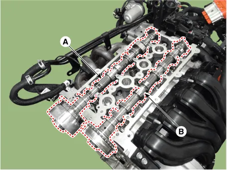
| 9. | Remove the exhaust camshaft (A) first, then intake camshaft (B).
|
| Inspection |
Camshaft
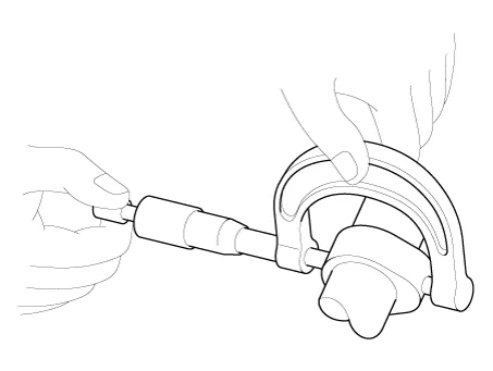
| 1. | Inspect cam lobes. Using a micrometer, measure the cam lobe height.
If the cam lobe height is less than standard, replace the camshaft. |
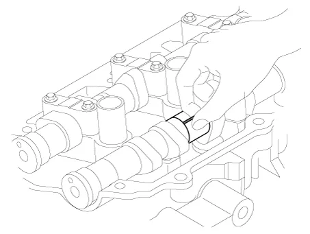
| 2. | Check the surface of the camshaft journal for wear. If the journal is worn excessively, replace the camshaft. |
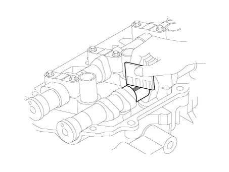
| 3. | Inspect the camshaft journal clearance.
|

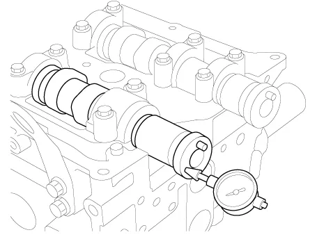
| 4. | Inspect the camshaft end play.
|
Continuously variable valve timing (CVVT) Assembly
| 1. | Inspect CVVT for smooth rotation.
|

| Installation |
| 1. | Install the exhaust camshaft (A) first, then intake camshaft (B).
|
| 2. | Install the front camshaft bearing cap (A) and the camshaft bearing caps (B) as following method with specified torque.
|
| 3. | Install the timing chain. (Refer to Timing System - "Timing Chain") |
| 4. | Install the timing chain cover. (Refer to Timing System - "Timing Chain Cover") |
| 5. | Install the cylinder head cover. (Refer to Cylinder Head Assembly - "Cylinder Head Cover") |
| 6. | Connect the High Voltage circuit. (Refer to General Information - "High Voltage Shutoff Procedure") |
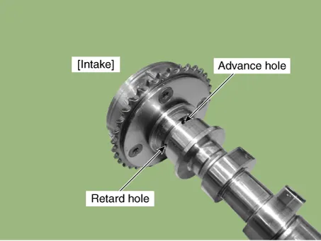
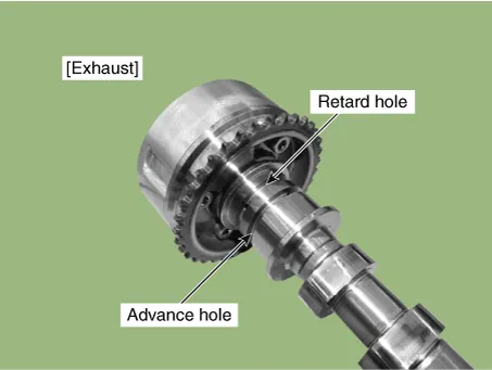
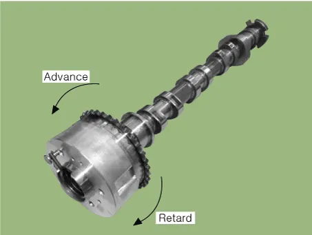
DescriptionThe continuous variable valve timing (CVVT) system advances or retards the opening of an intake or exhaust valve according to the ECM signals that are determined based on engine RPM and load.
Components1. Cylinder head assembly2. Cylinder head gasket3. Retainer lock4. Retainer5. Valve spring6. Valve stem seal7. Valve8. Swing arm9. Hydraulic lash adjuster (HLA)
Other information:
Hyundai Ioniq (AE) 2017-2022 Service & Repair Manual: Evaporator Temperature Sensor. Repair procedures
Inspection1.Turn the ignition switch OFF.2.Disconnect the evaporator temperature sensor connector.3.Measure the resistance between terminal "+" and "-" of the evaporator temperature sensor.Specification Evaporator core temperature [┬░C (┬░F)] Resistance [KŌä”]
Hyundai Ioniq (AE) 2017-2022 Service & Repair Manual: Warning Indicator. Components and components location
C
Categories
- Manuals Home
- Hyundai Ioniq Owners Manual
- Hyundai Ioniq Service Manual
- Jump starting procedure
- Brake System
- Checking the Coolant Level
- New on site
- Most important about car

Copyright ┬® 2026 www.hioniqae.com - 0.0096