
Hyundai Ioniq (AE): Floor Console / Floor Console Assembly. Repair procedures
| Replacement |
|

| 1. | Using a flat-tip screwdriver or remover, remove the gear knob & boot (A).
|

| 2. | Remove the gear knob & boots (A) pull both of it up.
|

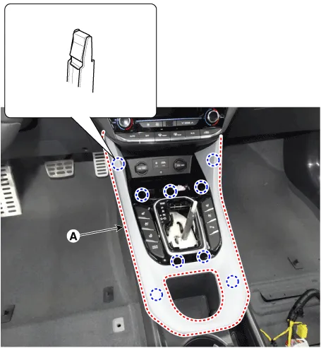
| 3. | Using a flat-tip screwdriver or remover, remove the console upper cover (A).
|
| 4. | Press the lock pin and separate the connectors (A).
|
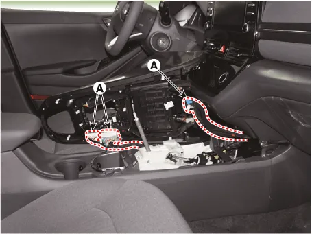
| 5. | Separate the power outlet connector (A).
|
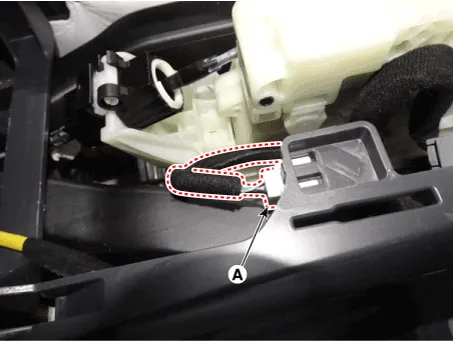
| 6. | Remove the storage box pad (A).
|

| 7. | Loosen the mounting clip and remove the console side cover (A).
|

| 8. | Loosen the mounting bolts, screws and remove the console complete assembly (A).
|
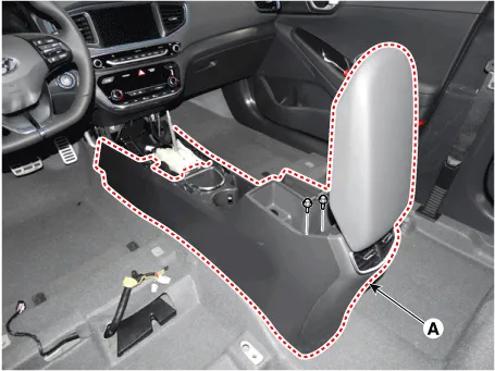
| 9. | To install, reverse the removal procedure.
|

Components1. Console complete assembly2. Console tray mat3. Console upper complete assembly 4. Floor console tray assembly 5. Front console side cover [LH]6.
Component Location 1. Rear console cover
Other information:
Hyundai Ioniq (AE) 2017-2022 Service & Repair Manual: A/C Pressure Transducer. Description and operation
DescriptionThe A/C Pressure Transducer (APT) converts the pressure value of high pressure line into voltage value after measuring it. By converted voltage value, engine ECU controls the cooling fan by operating it high speed or low speed. Engine ECU stops the operation of the compressor when the temperature of refrigerant line is very high or very
Hyundai Ioniq (AE) 2017-2022 Service & Repair Manual: Parking Distance Warning (PDW) Sensor. Repair procedures
Removal1.Disconnect the negative (-) battery terminal.2.Remove the front / rear bumper cover.(Refer to Body - "Front Bumper Cover")(Refer to Body - "Rear Bumper Cover")3.Disconnect the connector (A) from the parking assist sensor.4.Remove the sensor (A) by pulling out both ends of the sensor holder.
Categories
- Manuals Home
- Hyundai Ioniq Owners Manual
- Hyundai Ioniq Service Manual
- Engine Clutch System
- Body (Interior and Exterior)
- Repair procedures
- New on site
- Most important about car
