Hyundai Ioniq (AE): Crash Pad / Glove Box Upper Cover Assembly. Repair procedures
Hyundai Ioniq (AE) 2017-2022 Service & Repair Manual / Body (Interior and Exterior) / Crash Pad / Glove Box Upper Cover Assembly. Repair procedures
| Replacement |
|

| 1. | Remove the glove box. (Refer to Crash Pad - "Glove Box") |
| 2. | Remove the crash pad side cover [RH]. (Refer to Crash Pad - "Crash Pad Side Cover") |
| 3. | Remove the crash pad lower panel. (Refer to Crash Pad - "Crash Pad Lower Panel") |
| 4. | Loosen the mounting screw and remove the crash pad center garnish (A).
|
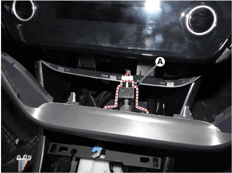
| 5. | Press the lock pin and separate the in-car sensor connector (A).
|
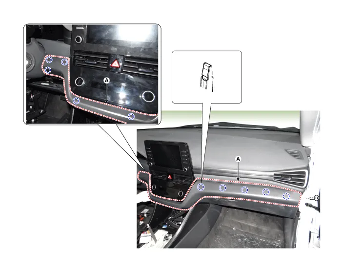
| 6. | Loosen the mounting screws, nuts and remove the glove box upper cover assembly (A).
|

| 7. | To install, reverse the removal procedure.
|

Component Location 1. Glove box upper cover assembly
Component Location 1. Main crash pad assembly
Other information:
Hyundai Ioniq (AE) 2017-2022 Service & Repair Manual: Intake Actuator. Specifications
S
Hyundai Ioniq (AE) 2017-2022 Service & Repair Manual: Front Radar Unit. Repair procedures
Removal1.Remove the front bumper.(Refer to Body - "Front Bumper")2.Disconnect the smart cruise control unit connector (A).3.Remove the smart cruise control nuit assembly (B) from thevehicle after loosening mounting bolts.Installation1.Install in the reverse order of removal.
Categories
- Manuals Home
- Hyundai Ioniq Owners Manual
- Hyundai Ioniq Service Manual
- Transmission Gear Oil. Repair procedures
- Engine Clutch System
- Brake System
- New on site
- Most important about car

Copyright © 2026 www.hioniqae.com - 0.0158