Hyundai Ioniq (AE): Engine Control System / Heated Oxygen Sensor (HO2S). Repair procedures
Hyundai Ioniq (AE) 2017-2022 Service & Repair Manual / Engine Control/Fuel System / Engine Control System / Heated Oxygen Sensor (HO2S). Repair procedures
| Inspection |
| 1. | Turn the ignition switch OFF. |
| 2. | Disconnect the HO2S connector. |
| 3. | Measure resistance between the HO2S terminals 2 and 5 [B1/S1]. |
| 4. | Measure resistance between the HO2S terminals 3 and 4 [B1/S2]. |
| 5. | Check that the resistance is within the specification.
|
| Removal |
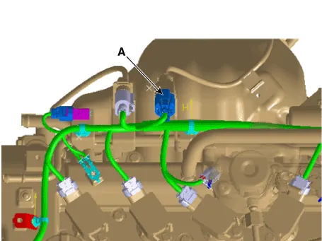
[Bank 1 / Sensor 1]
| 1. | Turn the ignition switch OFF and disconnect the battery negative (-) cable. |
| 2. | Disconnect the connector (A), and then remove the sensor (B).
|


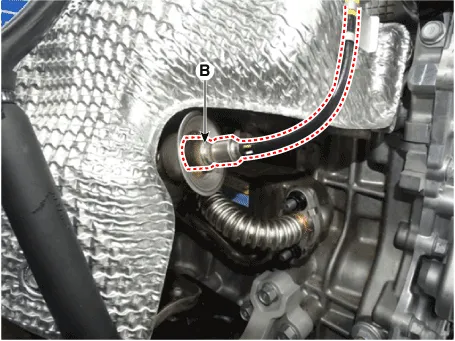
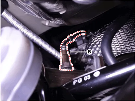
[Bank 1 / Sensor 2]
| 1. | Turn the ignition switch OFF and disconnect the battery negative (-) cable. |
| 2. | Disconnect the connector (A), and then remove the sensor (B).
|
| Installation |
|

|
| 1. | Install in the reverse order of removal.
|
Circuit Diagram
DescriptionInstalled in exhaust manifold, the Exhaust Gas Temperature Sensor (EGTS) #1 for EWGA senses the temperature of exhaust gas flowing into the EWGA.
Other information:
Hyundai Ioniq (AE) 2017-2022 Service & Repair Manual: Auto Defoging Actuator. Specifications
S
Hyundai Ioniq (AE) 2017-2022 Service & Repair Manual: Repair procedures
Service Point Target Auto Calibration (SPTAC)When you need calibration :– Front view camera is removed and mounted– Replace front view camera with a new one – Windshield glass changed– Front view camera coupler of the windshield glass is deformedService Point T
Categories
- Manuals Home
- Hyundai Ioniq Owners Manual
- Hyundai Ioniq Service Manual
- Engine Control/Fuel System
- Theft-alarm System
- Transmission Gear Oil. Repair procedures
- New on site
- Most important about car

Copyright © 2026 www.hioniqae.com - 0.0119