Hyundai Ioniq (AE): IMS(Integrated Memory System) / Memory power seat unit. Components and components location
Hyundai Ioniq (AE) 2017-2022 Service & Repair Manual / Body Electrical System / IMS(Integrated Memory System) / Memory power seat unit. Components and components location
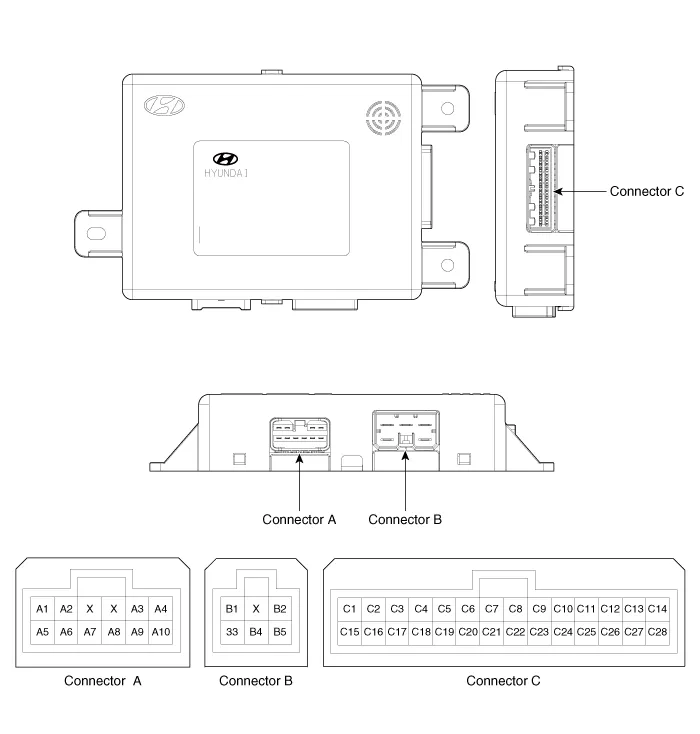
| Components |
|
No
|
Connecter A
|
Connecter B
|
Connecter C
|
| 1 | - | Battery (+) | Slide switch signal (Forward) |
| 2 | Reclining motor (Forward) | GND | Reclining switch signal (Forward) |
| 3 | Height motor (Up) | Battery (+) | Front tilt switch signal (Up) |
| 4 | Slide motor (Forward) | - | Reclining switch signal (Forward) |
| 5 | - | GND | - |
| 6 | Reclining motor (Backward) |   | B-CAN (High) |
| 7 | Tilt motor (Up) | B-CAN (Low) | |
| 8 | Tilt motor (Down) | IMS Switch 1 | |
| 9 | Height motor (Down) | Recline limit switch (Forward) | |
| 10 | Slide motor (Backward) | Slide sensor input | |
| 11 |   | Tilt sensor input | |
| 12 | - | ||
| 13 | Position sensor (Power) | ||
| 14 | IGN 1 | ||
| 15 | Slide switch (Backward) | ||
| 16 | Recline switch (Backward) | ||
| 17 | Tilt switch (Down) | ||
| 18 | Height switch (Down) | ||
| 19 | - | ||
| 20 | Ground | ||
| 21 | SET Switch | ||
| 22 | IMS Switch 2 | ||
| 23 | Recline limit switch (Backward) | ||
| 24 | Seat recline sensor | ||
| 25 | Seat height sensor (input) | ||
| 26 | - | ||
| 27 | - | ||
| 28 | Battery (+) |
DescriptionThe changed position of the seat by memorizing into the power seat unit with IMS switch controlling the optimal seat position set by the driver can be restored with the IMS switch.
Circuit Diagram
Other information:
Hyundai Ioniq (AE) 2017-2022 Service & Repair Manual: Intake Actuator. Specifications
S
Hyundai Ioniq (AE) 2017-2022 Service & Repair Manual: General safety information and caution
Safety PrecautionPrecautions To Take Before Servicing High Voltage System • Since hybrid vehicles contain a high voltage battery, if the high voltage system or vehicles are handled incorrectly, this might lead to a serious accidents like electric shock and electric leakage.
Categories
- Manuals Home
- Hyundai Ioniq Owners Manual
- Hyundai Ioniq Service Manual
- DCT(Dual Clutch Transmission) System
- Heating, Ventilation and Air Conditioning
- Repair procedures
- New on site
- Most important about car

Copyright © 2026 www.hioniqae.com - 0.0218