Hyundai Ioniq (AE): IMS(Integrated Memory System) / Memory power seat unit. Repair procedures
Hyundai Ioniq (AE) 2017-2022 Service & Repair Manual / Body Electrical System / IMS(Integrated Memory System) / Memory power seat unit. Repair procedures
| Removal |
| 1. | Disconnect the negative (-) battery terminal. |
| 2. | Remove the driver seat assembly. (Refer to Body - "Front Seat Assembly") |
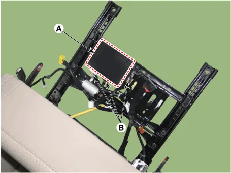
| 3. | Loosening the IMS unit mounting screws.
|

| 4. | Disconnect the IMS module connectors (B) and then remove the IMS unit (A).
|
| Installation |
| 1. | Install the memory power seat unit. |
| 2. | Install the driver seat assembly. |
| 3. | Connect the negative (-) battery terminal. |
Circuit Diagram
Other information:
Hyundai Ioniq (AE) 2017-2022 Service & Repair Manual: Evaporator Temperature Sensor. Description and operation
DescriptionThe evaporator temperature sensor will detect the evaporator core temperature and interrupt compressor relay power in order to prevent evaporator from freezing by excessive cooling. The evaporator temperature sensor has the Negative Temperature Coefficient (NTC).
Hyundai Ioniq (AE) 2017-2022 Service & Repair Manual: General safety information and caution
General Safety Information and CautionBe careful of the following precautions when driving the vehicle using the smart cruise control system. • The smart cruise control system may have limits in detecting distance to the vehicle ahead due to road and traffic conditions.
Categories
- Manuals Home
- Hyundai Ioniq Owners Manual
- Hyundai Ioniq Service Manual
- Jump starting procedure
- Repair procedures
- Transmission Gear Oil. Repair procedures
- New on site
- Most important about car

Copyright © 2026 www.hioniqae.com - 0.0139