Hyundai Ioniq (AE): Hybrid Motor Control System / Motor Control Unit(MCU). Schematic diagrams
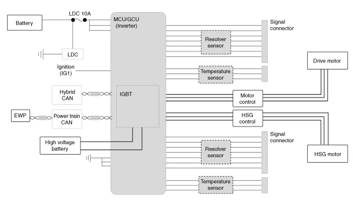
| Diagram System Circuit |
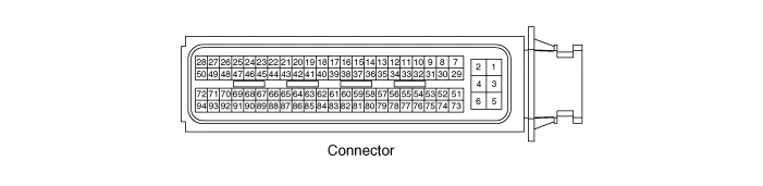
| MCU terminal input/output signal connector |
| Functions of MCU Terminal |
|
Terminal
|
Signal
|
Usage
|
| 5 | VB1 | Constant power (B+) |
| 6 | VB2 | Constant power (B+) |
| 3 | GND1 | Power ground |
| 4 | VB3 | Constant power (B+) |
| 1 | GND2 | Power ground |
| 2 | GND3 | Power ground |
| 73 | IGN | Ignition |
| 74 | - | |
| 75 | L_CAN_H | C_CAN_[High] |
| 76 | L_CAN_L | C_CAN_[Low] |
| 77 | - | |
| 78 | P_CAN_H | P - CAN [High] |
| 79 | P_CAN_L | P - CAN [Low] |
| 80 | - | |
| 81 | H_CAN_H | H - CAN [High] |
| 82 | H_CAN_L | H - CAN [Low] |
| 83 | - | |
| 84 | - | |
| 85 | - | |
| 86 | - | |
| 87 | H_REZ+ | HSG resolver (+) power |
| 88 | H_REZ- | HSG resolver (-) power |
| 89 | - | |
| 90 | - | |
| 91 | - | |
| 92 | - | |
| 93 | M_REZ+ | Motor resolver (+) power |
| 94 | M_REZ- | Motor resolver (-) power |
| 51 | - | |
| 52 | - | |
| 53 | - | |
| 54 | - | |
| 55 | - | |
| 56 | - | |
| 57 | - | |
| 58 | - | |
| 59 | - | |
| 60 | - | |
| 61 | - | |
| 62 | H_REZS1 | HSG resolver sensor (S1) input signal |
| 63 | H_REZS3 | HSG resolver sensor (S3) input signal |
| 64 | H_REZS2 | HSG resolver sensor (S2) input signal |
| 65 | H_REZS4 | HSG resolver sensor (S4) input signal |
| 66 | H_REZ_S | SHEILD |
| 67 | - | |
| 68 | M_REZS1 | Motor resolver sensor (S1) input signal |
| 69 | M_REZS3 | Motor resolver sensor (S3) input signal |
| 70 | M_REZS2 | Motor resolver sensor (S2) input signal |
| 71 | M_REZS4 | Motor resolver sensor (S4) input signal |
| 72 | M_REZ_S | SHEILD |
| 29 | - | |
| 30 | - | |
| 31 | ||
| 32 | ||
| 33 | ||
| 34 | ||
| 35 | - | |
| 36 | ||
| 37 | ||
| 38 | START_SIGNAL | Start signal input signal |
| 39 | - | |
| 40 | - | |
| 41 | - | |
| 42 | HSG_TM_GND | Sensor ground |
| 43 | HSG_TM | HSG temperature sensor input signal |
| 44 | HSG_TM_S | SHEILD |
| 45 | - | |
| 46 | - | |
| 47 | - | |
| 48 | MOT_TM_GND | Sensor ground |
| 49 | MOT_TM | Motor temperature sensor input signal |
| 50 | MOT_TM_S | SHEILD |
| 7 | - | |
| 8 | - | |
| 9 | - | |
| 10 | - | |
| 11 | - | |
| 12 | - | |
| 13 | - | |
| 14 | - | |
| 15 | BRAKE_SW2 | Brake switch 2 input signal (NC, IG1) |
| 16 | BRAKE_SW1 | Brake switch 1 input signal (NO, B+) |
| 17 | ||
| 18 | ||
| 19 | ||
| 20 | ||
| 21 | ||
| 22 | ||
| 23 | ||
| 24 | ||
| 25 | ||
| 26 | ||
| 27 | ||
| 28 |
| MCU terminal input/output signal |
|
Terminal
|
Signal
|
Usage
|
Condition
|
Type
|
Level
|
Waveform
|
| 5 | VB1 | Constant power (B+) | Constant | DC Voltage | Battery Power |   |
| 6 | VB2 | Constant power (B+) | Constant | DC Voltage | Battery Power |   |
| 3 | GND1 | Power ground | Constant | DC Voltage | Max. 50 mV | |
| 4 | VB3 | Constant power (B+) | Constant | DC Voltage | Battery Power | |
| 1 | GND2 | Power ground | Constant | DC Voltage | Max. 50 mV | |
| 2 | GND3 | Power ground | Constant | DC Voltage | Max. 50 mV |   |
| 73 | IGN | Ignition | IG ON | DC Voltage | Battery Power |   |
| 74 | - | |||||
| 75 | L_CAN_H | C - CAN [High] | IG ON | Pulse | Dominant : 2.75 - 4.5 (3.5) V Recessive : 2.0 - 3.0 (2.5) V |
|
| 76 | L_CAN_L | C - CAN [Low] | IG ON | Pulse | Recessive : 2.0 - 3.0 (2.5) V Dominant : 0.5 - 2.25 (1.5) V | |
| 77 | - | |||||
| 78 | P_CAN_H | P - CAN [High] | IG ON | Pulse | Dominant : 2.75 - 4.5 (3.5) V Recessive : 2.0 - 3.0 (2.5) V |
|
| 79 | P_CAN_L | P - CAN [Low] | IG ON | Pulse | Recessive : 2.0 - 3.0 (2.5) V Dominant : 0.5 - 2.25 (1.5) V | |
| 80 | - |   |   |   |   | |
| 81 | H_CAN_H | H - CAN [High] | IG ON | Pulse | Dominant : 2.75 - 4.5 (3.5) V Recessive : 2.0 - 3.0 (2.5) V |
|
| 82 | H_CAN_L | H - CAN [Low] | IG ON | Pulse | Recessive : 2.0 - 3.0 (2.5) V Dominant : 0.5 - 2.25 (1.5) V | |
| 83 | - |   | ||||
| 84 | - |   | ||||
| 85 | - | |||||
| 86 | - | |||||
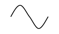
| 87 | H_REZ+ | HSG resolver (+) power | IG ON | Differential, Analog | 14 Vpp sine wave |
|
| 88 | H_REZ- | HSG resolver (-) power | ||||
| 89 | - |   |   |   |   | |
| 90 | - | |||||
| 91 | - |   | ||||
| 92 | - |   | ||||
| 93 | M_REZ+ | Motor resolver (+) power | IG ON | Differential, Analog | 14 Vpp sine wave |
|
| 94 | M_REZ- | Motor resolver (-) power | ||||
| 51 | - |   |   |   |   | |
| 52 | - |   |   |   |   | |
| 53 | - |   |   |   |   | |
| 54 | - | |||||
| 55 | - |   | ||||
| 56 | - |   | ||||
| 57 | - |   | ||||
| 58 | - |   | ||||
| 59 | - |   | ||||
| 60 | - |   | ||||
| 61 | - |   |   |   |   | |
| 62 | H_REZS1 | HSG resolver sensor (S1) input signal | IG ON | Differential, Analog | 0 - 3 Vpp sine wave |
|
| 63 | H_REZS3 | HSG resolver sensor (S3) input signal | ||||
| 64 | H_REZS2 | HSG resolver sensor (S2) input signal | IG ON | Differential, Analog | 0 - 3 Vpp sine wave |
|
| 65 | H_REZS4 | HSG resolver sensor (S4) input signal | ||||
| 66 | H_REZ_S | SHEILD | Constant | DC Voltage | Max. 50 mV | |
| 67 | - | |||||
| 68 | M_REZS1 | Motor resolver sensor (S1) input signal | IG ON | Differential, Analog | 0 - 3 Vpp sine wave |
|
| 69 | M_REZS3 | Motor resolver sensor (S3) input signal | ||||
| 70 | M_REZS2 | Motor resolver sensor (S2) input signal | IG ON | Differential, Analog | 0 - 3 Vpp sine wave |
|
| 71 | M_REZS4 | Motor resolver sensor (S4) input signal | ||||
| 72 | M_REZ_S | SHEILD | Constant | DC Voltage | Max. 50 mV | |
| 29 | - | |||||
| 30 | - | |||||
| 31 | ||||||
| 32 | ||||||
| 33 | ||||||
| 34 | ||||||
| 35 | - | |||||
| 36 | ||||||
| 37 | ||||||
| 38 | START_SIGNAL | Start signal input signal | IG ST | DC Voltage | Battery voltage | |
| 39 | - | |||||
| 40 | - | |||||
| 41 | - | |||||
| 42 | HSG_TM_GND | Sensor ground | Constant | DC Voltage | Max. 50 mV | |
| 43 | HSG_TM | HSG temperature sensor input signal | IG ON | Analog | 0 - 5V | |
| 44 | HSG_TM_S | SHEILD | Constant | DC Voltage | Max. 50 mV | |
| 45 | - | |||||
| 46 | - | |||||
| 47 | - | |||||
| 48 | MOT_TM_GND | Sensor ground | Constant | DC Voltage | Max. 50 mV | |
| 49 | MOT_TM | Motor temperature sensor input signal | IG ON | Analog | 0 - 5V | |
| 50 | MOT_TM_S | SHEILD | Constant | DC Voltage | Max. 50 mV | |
| 7 | - | |||||
| 8 | - | |||||
| 9 | - | |||||
| 10 | - | |||||
| 11 | - | |||||
| 12 | - | |||||
| 13 | - | |||||
| 14 | - | |||||
| 15 | BRAKE_SW2 | Brake switch 2 input signal (NC, IG1) | IG ON | DC Voltage | Battery voltage | |
| 16 | BRAKE_SW1 | Brake switch 1 input signal (NO, B+) | Constant | DC Voltage | Battery voltage | |
| 17 | ||||||
| 18 | ||||||
| 19 | ||||||
| 20 | ||||||
| 21 | ||||||
| 22 | ||||||
| 23 | ||||||
| 24 | ||||||
| 25 | ||||||
| 26 | ||||||
| 27 | ||||||
| 28 |


Component location1. HPCU (Hybrid Power Control Unit)(LDC+MCU+HCU+Reservoir)2. Hybrid drive motor3. Hybrid starter generator (HSG)4. Electrical radiator5.
Removal • MCU is integrated with HPCU. Therefore, to install / remove the MCU, follow the procedure for installing / removing the HPCU.
Other information:
Hyundai Ioniq (AE) 2017-2022 Service & Repair Manual: In-car Sensor. Description and operation
DescriptionThe In-car air temperature sensor is built in the heater & A/C control unit.The sensor contains a thermistor which measures the temperature of the inside. The signal decided by the resistance value which changes in accordance with perceived inside temperature, is delivered to heater control unit and according to this signal the contr
Hyundai Ioniq (AE) 2017-2022 Service & Repair Manual: Ambient Temperature Sensor. Description and operation
DescriptionThe ambient temperature sensor is located at the front of the condenser and detects ambient air temperature. It is a negative type thermistor; resistance will increase with lower temperature, and decrease with higher temperature.The sensor output will be used for discharge temperature control, temperature regulation door contrl, blower m
Categories
- Manuals Home
- Hyundai Ioniq Owners Manual
- Hyundai Ioniq Service Manual
- Engine Mechanical System
- If the 12 Volt Battery is Discharged (Hybrid Vehicle)
- Brake System
- New on site
- Most important about car
