Hyundai Ioniq (AE): Hybrid Motor Control System / Motor Control Unit(MCU). Components and components location
| Component location |
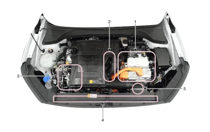
| 1. HPCU (Hybrid Power Control Unit) (LDC+MCU+HCU+Reservoir) 2. Hybrid drive motor | 3. Hybrid starter generator (HSG) 4. Electrical radiator 5. Electric water pump (EWP) |
| Components |
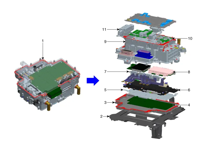
| 1. HPCU (Hybrid Power Control Unit) 2. HPCU tray 3. HPCU cover 4. Integrated board (MCU / HCU / LDC) 5. Shield plate 6. Capacitor | 7. Current sensor module 8. Gate board + Power module 9. Heat sink (water - cooled) 10. LDC (Low voltage DC - DC Converter) 11. High - voltage junction box |
| • | An inverter supplies AC current to the drive motor and HSG. |
| • | Depending on the driving conditions, the drive motor and HSG of the integrated board (control board) may act as a generator. |
| • | One CPU controls two motors (drive motor and HSG) |
| • | Sensors send the position, current, and temperature information to the CPU. The CPU generates the pulse width modulation signal and sends it to the gate board. |
| • | Capacitor is an energy storage device for smoothing the current. |
| • | Current sensor measures the current that flows through the motor, and is attached to each phase of a 3 - phase busbar. |
| • | Power module has six switches that are used to convert DC current to AC current. |
| • | Heat sink dissipates the heat of the coolant and is located between the power module and the cooling path. |
DescriptionIn a hybrid electric vehicle, HCU (an upper level controller), LDC (power converter), and inverter are integrated in the HPCU. HPCU is located on the left side of the engine compartment.
Diagram System CircuitA high-capacity power module is applied to the two high-voltage motors.The power module consists of a high - speed switching circuit that is isolated from the IGBT and DIODE circuits.
Other information:
Hyundai Ioniq (AE) 2017-2022 Service & Repair Manual: Auto Defoging Actuator. Repair procedures
Inspection1.Turn the ignition switch OFF. 2.Disconnect the auto defogging connector. 3.Verify that the auto defogging actuator operates to the open position when connecting 12V to terminal 3 and grounding terminal 4. Verify that the auto defogging actuator operates to the close position when connected in reverse.
Hyundai Ioniq (AE) 2017-2022 Service & Repair Manual: Parking Distance Warning (PDW) ON/OFF Switch. Repair procedures
Removal • Put on gloves to prevent hand injuries. • When removing with a flat-tip screwdriver or remover, wrap protective tape around the tools to prevent damage to components.
Categories
- Manuals Home
- Hyundai Ioniq Owners Manual
- Hyundai Ioniq Service Manual
- Repair procedures
- Hybrid Vehicle Engine Compartment
- Checking the Coolant Level
- New on site
- Most important about car
