Hyundai Ioniq (AE): Heater / Auto Defoging Actuator. Repair procedures
| Inspection |
| 1. | Turn the ignition switch OFF. |
| 2. | Disconnect the auto defogging connector. |
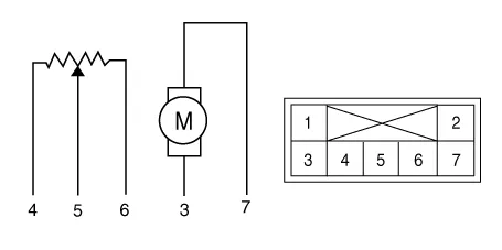
| 3. | Verify that the auto defogging actuator operates to the open position when connecting 12V to terminal 3 and grounding terminal 4. Verify that the auto defogging actuator operates to the close position when connected in reverse.
|
| 4. | Connect the auto defogging actuator connector. |
| 5. | Turn the ignition switch ON. |
| 6. | Check the voltage between terminals 6 and 5. |
| 7. | If the measured voltage is not within specification, check the operation by replacing the existing auto defogging actuator with a new genuine part. After that, determine whether replacement of the auto defogging actuator is required or not. |
| Diagnosis With GDS |
| 1. | The heating, ventilation and air conditioning can be quickly diagnosed failed parts with vehicle diagnostic system (GDS). ※ The diagnostic system (GDS) provides the following information. (1) Self diagnosis : Checking the failure code (DTC) and display. (2) Current data : Checking the system input/output data state. (3) Actuation test : Checking the system operation condition. (4) Additional function : Other controlling such as he system option and zero point adjustment. |
| 2. | Select the 'Car model' and the system to be checked in order to check the vehicle with the tester. |
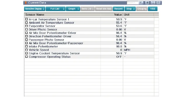
| 3. | Select the 'Current data' menu to search the current state of the input / output data. The input / output data for the sensors corresponding to the Auto Defogging Actuator can be checked.
|
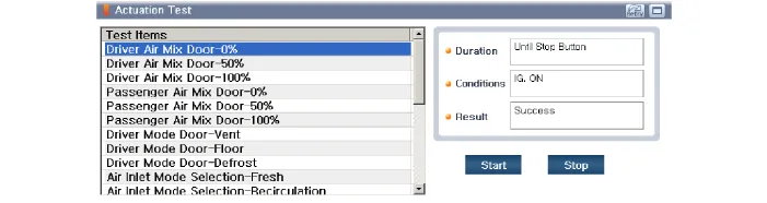
| 4. | To perform compulsory operation on Auto Defogging Actuator input factors, select "ACTUATION TEST".
|
| Replacement |
| 1. | Disconnect the negative (-) battery terminal. |
| 2. | Remove the main crash pad assembly. (Refer to Body - "Main Crash Pad Assembly") |
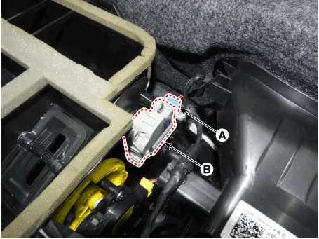
| 3. | Disconnect the connector (A) and then remove the auto defogging actuator (B) after loosening the mounting screws.
|
| 4. | To install, reverse the removal procedure. |
Specifications Door position Voltage (V) Error detecting Vent4.7 ± 0.15Low voltage : 0.
Other information:
Hyundai Ioniq (AE) 2017-2022 Service & Repair Manual: Smart Cruise Control (SCC) Switch. Repair procedures
Removal1.Disconnect the negative (-) battery terminal.2.Remove the steering wheel assembly.(Refer to Steering System -"Steering Wheel")3.Remove the steering back cover (A).4.Remove the steering remote control connector (A).5.Remove the steering remote control (A), after loosening the screws.
Hyundai Ioniq (AE) 2017-2022 Service & Repair Manual: Repair procedures
Diagnosis with GDS1.REAR CORENER RADAR system defects can be quickly diagnosed with the GDS. GDS operates actuator quickly to monitor, input/output value and self diagnosis.2.Connect the cable of GDS to the data link connector in driver side crash pad lower panel, turn the power on GDS.
Categories
- Manuals Home
- Hyundai Ioniq Owners Manual
- Hyundai Ioniq Service Manual
- Engine Clutch System
- Suspension System
- Jump Starting
- New on site
- Most important about car
