Hyundai Ioniq (AE): Seat Electrical / Power Seat Control Switch. Schematic diagrams
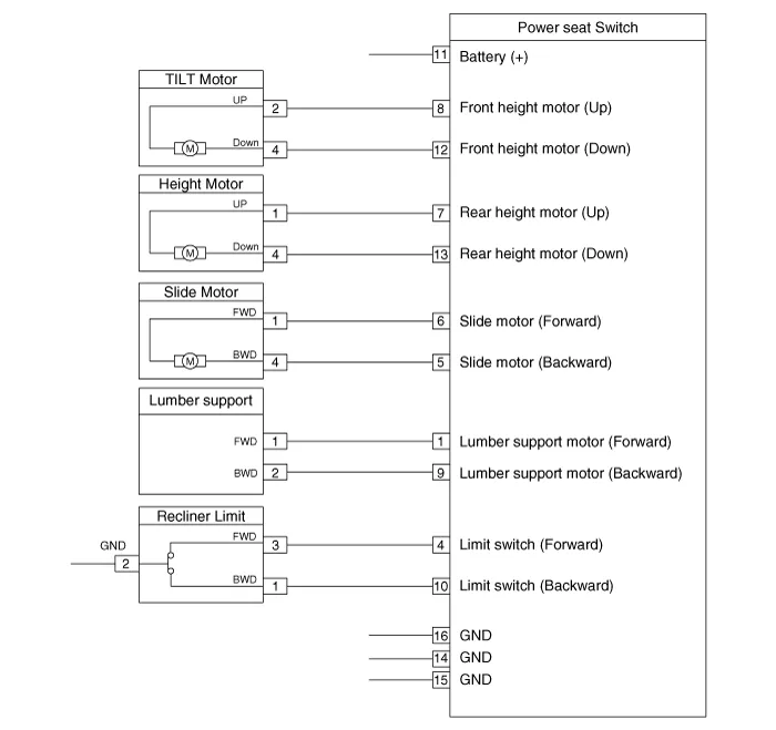
| Circuit Diagram |
InspectionDiagnosis with GDS1.The body electrocal system can be quickly diagnosed failed parts with vehicle diagnostic system (GDS).The diagnostic system (GDS) provides the following information.
InspectionSeat Control Switch1.With the power seat switch in each position, make sure that continuity exists between the terminals below. If continuity is not as specified, replace the power seat switch.
Other information:
Hyundai Ioniq (AE) 2017-2022 Service & Repair Manual: Auto Defogging Sensor. Description and operation
DescriptionThe auto defogging sensor is installed on the front window glass. The sensor judges and sends signal if moisture occurs to blow out wind for defogging. The air conditioner control module receives signal from the sensor and restrains moisture and eliminate defog by controlling the intake actuator, A/C, auto defogging actuator, blower moto
Hyundai Ioniq (AE) 2017-2022 Service & Repair Manual: Repair procedures
Diagnosis with GDS1.REAR CORENER RADAR system defects can be quickly diagnosed with the GDS. GDS operates actuator quickly to monitor, input/output value and self diagnosis.2.Connect the cable of GDS to the data link connector in driver side crash pad lower panel, turn the power on GDS.
Categories
- Manuals Home
- Hyundai Ioniq Owners Manual
- Hyundai Ioniq Service Manual
- Engine Clutch System
- Transmission Gear Oil. Repair procedures
- How to Connect Portable Charger (ICCB: In-Cable Control Box)
- New on site
- Most important about car
